Slings are the most commonly used piece of materials handling apparatus. They are used with material handling equipments like cranes, chain pulley blocks, etc. to hold suspended loads. Based on type of construction, there are mainly three types of slings. They are single leg sling, multiple leg sling (for bridal hitch with two, three or four legs) and end less sling (grommet type). Numerous sling end configurations and fittings/attachments are available for various applications.
There are six types of slings based on material of manufacture – wire rope slings, alloy steel chain slings, synthetic web slings, synthetic round slings, metal mesh slings and fibre rope slings. Information about these slings is given in this article.
Click on a link below to jump to a topic or read all.
Wire Rope Slings
Alloy Steel Chain Slings
Synthetic Web Slings
Synthetic Round Slings
Metal Mesh Slings
Natural and Synthetic Fibre Rope Slings
General Recommendations on Use of Slings
Wire Rope Slings
Wire rope slings are a basic material handling tool and are the most frequently used type of slings in industry. Wire rope slings are made from wire ropes with either Independent Wire Rope Core (IWRC) or a fiber core. A sling manufactured with a fiber core is usually more flexible but is less resistant to environmental damage. Sling made of an independent wire rope core has greater strength and is more resistant to heat damage. Mostly slings are made from wire rope having right hand regular lay of 6×19 or 6×37 construction. Wire rope slings are made from various grades of wire rope, but the most common grades in use are Improved Plow Steel, Extra Improved Plow Steel (EIPS) and Extra Extra Improved Plow Steel (EEIPS).
Construction
Slings ends are generally made with plain loops or with thimbles.
Sling with Plain Loops
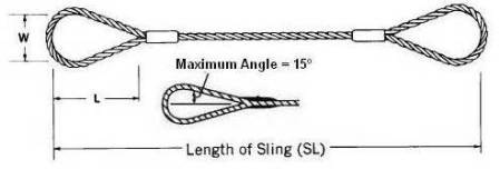
Sling with plain loops at both ends is used for general purpose lifting. The sling eye shall have maximum angle of 15 º a shown above. Generally the eye dimensions are W = 8d and L = 16d where d = wire rope diameter.
Sling with Thimbles
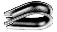
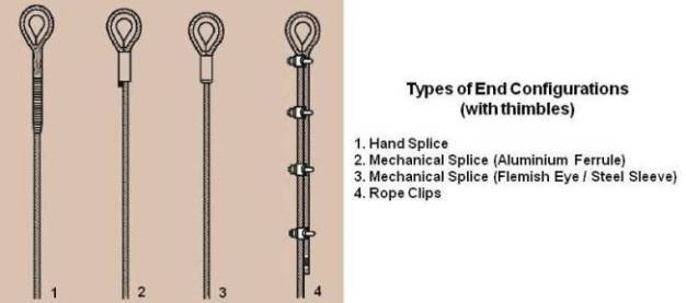
Thimble (shown above) is the reinforcing member of a rope eye. It protects the rope at the point of attachment. Thimbles are fitted to sling ends to protect the rope against wear and abrasion from hooks, links, pins, etc. Heavy duty thimbles are used for protection against concentrated wear. Commonly used sling end configurations with thimbles are shown below.
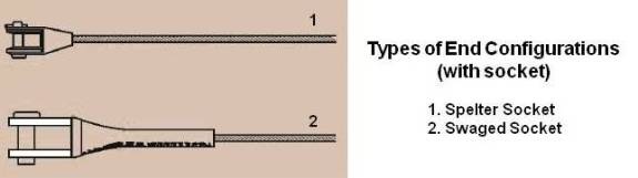
Sometime spelter or swaged type sockets are fitted at the end of a wire rope as shown below.
Sling ends are made by hand splicing, mechanical splicing or by rope clips as under.
Hand Splicing
Hand splice is made by forming an eye and "tucking" and "locking" a strand of the wire rope under other adjacent strands (interweaving the wire rope strands). Splicing by this method requires skill, is time consuming and requires long rope. The method is now replaced by mechanical splicing.
Mechanical Splicing
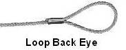
In mechanical splicing, the end of wire rope after forming an eye is secured to the sling body (wire rope) by pressing a metal sleeve/ferrule. A hydraulic swaging press with special dies is used to bond the sleeve in place. Extreme pressure forces the sleeve material to flow into the voids between the wires and strands, creating an assembly that maintains most of the wire rope's nominal breaking strength. This type of eye is known as loop back eye.
Flemish Eye
In Flemish Eye, the rope firstly undergoes a limited form of hand spliceing (Flemish Splicing) which is then completed by mechanically swaging a steel sleeve/ferrule over the ends of the rope as shown below.
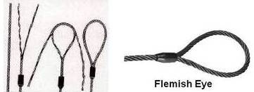
Flemish eye is fabricated by unlaying the rope body into two parts, one having three strands, the other having the remaining three strands and core. The rope is unlayed far enough back to allow the eye to be formed by looping one part in one direction and the other part in the opposite direction and laying the rope back together. The strands are rolled back around the rope body and a metal sleeve is slipped over the ends and pressed (swaged) to secure the ends to the sling body.
Rope Clips/Clamps
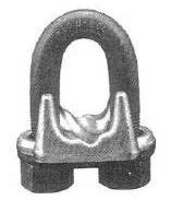
It is recommended not to use wire rope clips (shown above) to fabricate wire rope slings, except where the application precludes the use of prefabricated slings and where the sling is designed for the specific application by a qualified person. It is also advised not to use slings made with wire rope clips in a choker hitch. If sling ends are fabricated by wire rope clips, they shall be made of drop forged steel and using adequate number of clips at recommended spacing. U bolt of a clip shall be fitted over the dead end of the rope and the live rope shall rest in the clip saddle. The clips shall be evenly tightened to recommended torque before and after the initial load is applied and shall be inspected regularly to ensure that the recommended torque remains.
Slings fabricated using wire rope clips shall be de-rated to 80% of the rated wire rope load capacity to account for the efficiency of the clips.
Swage Fittings and Spelter Sockets
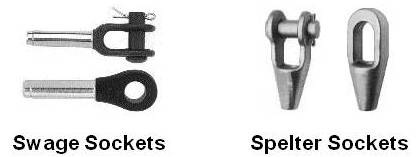
Above picture shows open and closed type of swage and spelter sockets.
In case of swage fitting, a wire rope end is inserted into the fitting bore and swaged onto the rope (like mechanical splicing).
In case of a spelter socket, a wire rope end is inserted in the socket and attached to it by pouring molten metal (Zinc or White Metal) or resin in the fitting basket (cup).
For more information on spelter socketing procedures, please refer following standards.
IS 3937: Recommendation for socketing of wire ropes (Part 1: with Zinc, Part 2: with White Metal and Part 3: with resins).
ISO 7595: Socketing procedures for wire ropes―Molten metal socketing.
ISO 7596: Socketing procedures for wire ropes―Resin sockting.
For more information on splicing, please refer IS 5245 as under.
IS 5245, Part 1: Methods for splicing of wire ropes, Part 1 – Hand splicing of wire ropes.
IS 5245, Part II: Methods for splicing of wire ropes, Part II – Wire rope sling legs with Ferrule-Secured eye terminals.
Braided and Cable-Laid Slings
Braided Sling
8-part braided slings are fabricated from 8 pieces of small diameter wire ropes, braided together to form one large sling. They can be either flat or round. They are commonly used for high capacity lifts. They snug tightly to a load in a choker hitch, resist kinking and offer the ultimate in flexibility.
Cable-Laid Sling
Cable-laid slings are fabricated from a rope comprised of 7 small wire ropes. This construction creates a very pliable sling and is used where flexibility and resistance to kinking are more important than resistance to abrasion. Since the rope is made up of many smaller wire ropes, the sling can bend around smaller diameters without taking a permanent set or kink. The small wires, however, are susceptible to abrasion.
Minimum Length of a Sling
It is recommended to have minimum length of sling as under.
Slings made of rope with 6×19 and 6×37 classifications and cable slings should have a minimum clear length of rope 10 times the component rope diameter between splices, sleeves, or end fittings.
Braided slings should have a minimum clear length of rope 40 times the component rope diameter between the loops or end fittings.
Grommets and endless slings should have a minimum circumferential length of 96 times the body diameter of the grommet or endless sling.
Proof Loads
Wire rope sling assemblies shall be proof tested using the following criteria:
Hand Tucked: The proof load for hand-tucked slings shall be a minimum of the rated load and shall not exceed 1.25 times the rated load.
Wire Rope Clips: The proof load for wire rope clip slings shall be a minimum of the rated load and shall not exceed two times the rated load.
Others Configurations: The proof load for other types of slings including mechanical splice, zinc-poured, resin poured, and swaged socket shall be two times the rated load.
Multiple Leg Slings: The proof load for multiple-leg bridle slings shall be applied to the individual legs. The proof load for the individual legs shall be consistent with the particular single-leg assembly stated above. Any master link to which multiple legs are connected shall be proof loaded to two times the force applied by the combined legs.
D/d Ratio
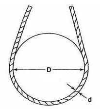
The capacity of a wire rope sling can be greatly affected by being bent sharply around pins, hooks, or parts of a load. The wire rope industry uses the term “D/d ratio” to express the severity of bend. “D” is diameter of curvature that the rope or sling is subjected to and “d” is the diameter of the rope. The minimum D/d ratio is usually taken as 20 which correspond to 92 % efficiency.
Rated Loads / Capacity
Safe Working Load (SWL) Limit / Rated Capacity of a sling depend on strength of material (wire rope), fabrication efficiency and design factor (factor of safety).
Rated capacities (SWL) of commonly used single leg slings for vertical lifting expressed in Tons (2000 lb) are as given under. Rated loads in the tables are based on design factor of 5 and minimum D/d ratio of 25/1.
Wire Rope Classification: 6×19 or 6×37
Type of Core: Fiber Core (FC)
Wire Rope Grade (Tensile Strength): Extra Improved Plow Steel (EIPS) Grade
| Rope Diameter inch | Rated Capacity in Tons (2000 lb) | ||
|---|---|---|---|
| Hand-tucked splice | Mechanical splice | Swaged or poured (spelter) socket | |
| ¼ | 0.54 | 0.56 | 0.60 |
| 5/16 | 0.83 | 0.87 | 0.94 |
| 3/8 | 1.2 | 1.2 | 1.3 |
| 7/16 | 1.6 | 1.7 | 1.8 |
| ½ | 2.0 | 2.2 | 2.4 |
| 9/16 | 2.5 | 2.7 | 3.0 |
| 5/8 | 3.1 | 3.4 | 3.7 |
| ¾ | 4.3 | 4.8 | 5.2 |
| 7/8 | 5.7 | 6.6 | 7.1 |
| 1 | 7.4 | 8.3 | 9.2 |
| 1 1/8 | 9.3 | 10 | 12 |
| 1 1/4 | 11 | 13 | 14 |
Wire Rope Classification: 6×19 or 6×37
Type of Core: Independent Wire Rope Core (IWRC)
Wire Rope Grade (Tensile Strength): Extra Improved Plow Steel (EIPS) Grade
| Rope Diameter inch | Rated Capacity in Tons (2000 lb) | ||
|---|---|---|---|
| Hand-tucked splice | Mechanical splice | Swaged or poured (spelter) socket | |
| ¼ | 0.54 | 0.65 | 0.68 |
| 5/16 | 0.83 | 1.0 | 1.1 |
| 3/8 | 1.2 | 1.4 | 1.5 |
| 7/16 | 1.6 | 1.9 | 2.0 |
| ½ | 2.0 | 2.5 | 2.7 |
| 9/16 | 2.5 | 3.2 | 3.4 |
| 5/8 | 3.1 | 3.9 | 4.1 |
| ¾ | 4.3 | 5.6 | 5.9 |
| 7/8 | 5.7 | 7.6 | 8.0 |
| 1 | 7.4 | 9.8 | 10 |
| 1 1/8 | 9.3 | 12 | 13 |
| 1 1/4 | 11 | 15 | 16 |
| 1 3/8 | 14 | 18 | 19 |
| 1 ½ | 16 | 21 | 23 |
| 1 5/8 | 19 | 24 | 26 |
| 1 ¾ | 22 | 28 | 31 |
| 1 7/8 | 25 | 32 | 35 |
| 2 | 28 | 37 | 40 |
Wire Rope Classification: 6×19 or 6×37
Type of Core: Independent Wire Rope Core (IWRC)
Wire Rope Grade (Tensile Strength): Extra Extra Improved Plow Steel (EEIPS) Grade
| Rope Diameter inch | Rated Capacity in Tons (2000 lb) | ||
|---|---|---|---|
| Hand-tucked splice | Mechanical splice | Swaged or poured (spelter) socket | |
| ¼ | 0.60 | 0.71 | 0.74 |
| 5/16 | 0.92 | 1.1 | 1.2 |
| 3/8 | 1.3 | 1.6 | 1.7 |
| 7/16 | 1.7 | 2.1 | 2.2 |
| ½ | 2.2 | 2.8 | 2.9 |
| 9/16 | 2.8 | 3.5 | 3.7 |
| 5/8 | 3.4 | 4.3 | 4.5 |
| ¾ | 4.7 | 6.2 | 6.5 |
| 7/8 | 6.2 | 8.3 | 8.8 |
| 1 | 8.1 | 11 | 11 |
| 1 1/8 | 10 | - | 14 |
| 1 1/4 | 13 | - | 18 |
| 1 3/8 | 15 | - | 21 |
| 1 ½ | 18 | - | 25 |
| 1 5/8 | 21 | - | 29 |
| 1 ¾ | 24 | - | 34 |
| 1 7/8 | 27 | - | 38 |
| 2 | 31 | - | 43 |
Indian sling manufacturers generally offer following two types of mechanically spliced slings in wire rope construction 6×19 or 6×37.
1. Wire rope with fibre core made from galvanized wire as per Grade 1570 (160 Kgf / mm2).
2. Wire rope with steel core made from black wire as per Grade 1770 (180 Kgf / mm2 = Improved Plow Steel).
Rated capacities (SWL) of these single leg slings for vertical lifting expressed in Tonne (1000 Kgf) based on design factor of 5 are as under.
| Rope Diameter mm | Safe Working Load in Tonnes (1 Tonne = 1000 Kgf) | |
|---|---|---|
| Galvanized wire as per Grade 1570 | Black wire as per Grade 1770 | |
| 6 | 0.32 | - |
| 7 | 0.43 | - |
| 8 | 0.57 | 0.81 |
| 9 | 0.72 | 1.04 |
| 10 | 0.89 | 1.2 |
| 11 | 1.1 | 1.5 |
| 12 | 1.3 | 1.8 |
| 13 | 1.5 | 2.1 |
| 14 | 1.7 | 2.5 |
| 16 | 2.3 | 3.2 |
| 18 | 2.9 | 4.1 |
| 20 | 3.6 | 5.1 |
| 2 | 4. | 6.2 |
| 24 | 5.1 | 7.4 |
| 26 | 6.0 | 8.6 |
| 28 | 7.0 | 10.0 |
| 32 | 9.1 | 13.1 |
| 36 | - | 16.6 |
| 40 | - | 20.5 |
| 44 | - | 24.8 |
| 48 | - | 29.5 |
| 52 | - | 34.8 |
Note:
Generally wire rope of 6×19 classification is used for wire rope diameter up to and including 1 inch. For wire rope diameter larger than 1 inch, 6×37 classification is used.
IS 2762: Specification for wire rope slings and sling legs covers dimensions, construction, loading, tests and marking of one-, two-, three- and four-leg slings for wire ropes of nominal diameter 8 to 44 mm, having legs of following types:
a) Single part spliced,
b) Double part spliced endless, and
c) Double part grommet.
To get lighter slings, please specify wire rope with independent wire rope core (IWRC) made from wires having higher tensile strength (say 220 Kgf /mm2 which is equivalent to grade 2160 / Extra Extra Improved Plow Steel Grade) and factor of safety = 5.
Construction Safety Association of Ontario recommends to use wire rope slings made from from improved plow steel with independent wire rope core to reduce the risk of crushing.
Attachments
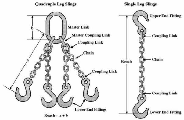
Various types of attachments like link, hook, swivel hook, plate lifting clamp, etc. are attached to sling eyes for various applications. When two or more slings are connected to a common link for make a lifting bridal, the assembly is called multiple leg sling.
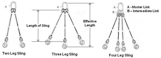
Above picture shows two, three and four leg slings with oblong link and eye hooks. Three and four leg slings are used for level lifting of a load.
When using a multiple leg sling, ensure that the rating shown for the single leg sling is not exceeded in any leg of the multiple leg sling.
All attachments shall have a rated capacity equal to or greater than that of the wire rope sling.
Ensure that all welded end attachments are tested by the manufacturer or equivalent entity at twice their rated capacity before initial use.
Effect of Environment
Permanently remove from service fiber core wire rope slings of any grade if they are exposed to temperatures in excess of 180º F (82º C).
Follow the recommendations of the sling manufacturer when you use metallic core wire rope slings of any grade at temperatures above 400º F (204º C) or below minus 40º F (minus 40º C).
Inspection and Removal
Make periodic inspections of slings at intervals not greater than 12 months. Do not inspect a sling by passing bare hands over the wire rope body. Broken wires, if present, may puncture the hands. Deterioration that would result in loss of original strength shall be observed. Remove sling from service if any of the following conditions are present:
- Severe localized abrasion or scraping of one-third the original diameter of outside individual wires.
- Kinking, crushing, bird caging or any other damage resulting in distortion of the rope structure.
- Evidence of heat damage.
- End attachments that are cracked, deformed, or worn to the extent that the strength of the sling is substantially affected.
- Severe corrosion of the rope or end attachments.
- For strand-laid and single-part slings, ten randomly distributed broken wires in one rope lay or five broken wires in one strand in one rope lay.
- Broken wires in braided and cable-laid slings as per table given below.
| Sling body | Allowable broken wires per lay or one braid | Allowable broken strands per sling length |
|---|---|---|
| Less than eight-part braid | 20 | 1 |
| Eight-part braid and more | 40 | 1 |
| Cable laid | 20 | 1 |
Recommendations on Use of Wire Rope Slings
Use wire rope slings with independent wire rope core (IWRC) to reduce the risk of crushing.
All eyes be fitted with thimbles and formed by Flemish Splice and secured by swaged or pressed ferrules/sleeves (mechanical splicing). Flemish Eye has reserve strength in case of failure of ferrule/sleeve.
Wire rope slings shall not be shortened or lengthened by knotting or twisting or with wire rope clips or other methods not approved by the sling manufacturer.
Do not subject fiber core wire rope slings to degreasing or to a solvent because of possible damage to the core.
Wire rope wedge sockets shall not be used to fabricate wire rope slings.
Go to Top
Alloy Steel Chain Slings
Chain slings are used for application requiring flexibility and resistance to abrasion, cutting and high temperatures.
Construction and Rated Loads
Chain slings used for overhead lifting applications must be manufactured from alloy steel. Alloy steel chain slings are made from various grades of alloy, but the most common grades in use are grades 80 and 100. Rated loads for alloy steel chain slings shall be based on a minimum design factor of 4. If other grades of chain are used, use them in accordance with the manufacturer's recommendations and guidance. The general configuration of a chain sling is as shown below.
Rated loads (with Design Factor = 4) for vertical lift of single leg alloy steel Grade 80 and Grade 100 chain slings are as shown under.
| Nominal Chain Size | Rated Load in lb | ||
|---|---|---|---|
| inch | mm | Alloy Steel Chain Grade 80 | Alloy Steel Chain Grade 100 |
| 7/32 | 5.5 | 2,100 | 2,700 |
| 9/32 | 7 | 3,500 | 4,300 |
| 5/16 | 8 | 4,500 | 5,700 |
| 3/8 | 10 | 7,100 | 8,800 |
| 1/2 | 13 | 12,000 | 15,000 |
| 5/8 | 16 | 18,100 | 22,600 |
| 3/4 | 20 | 28,300 | 35,300 |
| 7/8 | 22 | 34,200 | 42,700 |
| 1 | 26 | 47,700 | - |
| 1-1/4 | 32 | 72,300 | - |
Note:
As per Construction Safety Association of Ontario, like all other slings and attachments, chain slings and attachments must have design factor (factor of safety) of 5.
IS 2760: Specification for steel chain slings covers the requirements, methods of rating and testing of single-, two-, three- and four-leg or branch welded chain slings of Grades L (3), M (4), S (6) and T (8) using chains conforming to IS 2429 : Part I : 1970, IS 3109 : Part I : 1970, IS 6217 : 1971 and IS 6215 : 1971 respectively together with the appropriate range of components.
Attachments
All attachments shall have a rated capacity at least equal to that of the steel chain with which they are used.
All welded components in the sling assembly shall be proof-load tested as components or as part of the sling assembly.
Where used, handles shall be welded to the master link or hook before heat treatment (This prohibits welding on chain slings during field operations.).
Effect of Temperature
If the chain sling gets heated to a temperature above 400°F (204°C), rated loads shall be reduced in accordance with the chain manufacturer’s recommendations regarding usage both while heated and after being heated. If chain slings are to be used in temperatures of -40°F (-40°C) or less, the manufacturer should be consulted.
Typical reduction of chain sling’s rated load (Safe Working Load) according to temperature is as under.
| Temperature | Grade of Chain | ||||
|---|---|---|---|---|---|
| Grade 80 | Grade 100 | ||||
| (°F) | (°C) | Temporary Reduction of Rated Load WHILE AT Temperature |
Permanent Reduction of Rated Load AFTER EXPOSURE to Temperature |
Temporary Reduction of Rated Load WHILE AT Temperature |
Permanent Reduction of Rated Load AFTER EXPOSURE to Temperature |
| Below 400 | Below 204 | NONE | NONE | NONE | NONE |
| 400 | 204 | 10% | None | 15% | None |
| 500 | 260 | 15% | None | 25% | 5% |
| 600 | 316 | 20% | 5% | 30% | 15% |
| 700 | 371 | 30% | 10% | 40% | 20% |
| 800 | 427 | 40% | 15% | 50% | 25% |
| 900 | 482 | 50% | 20% | 60% | 30% |
| 1000 | 538 | 60% | 25% | 70% | 35% |
| Over 1000 | Over 538 | REMOVE FROM SERVICE | |||
Inspection, Repairing / Reconditioning and Removal
Make periodic inspections of steel chain slings at intervals no greater than 12 months.
Make a thorough inspection of slings and attachments. Look for wear, defective welds, nicks, cracks, breaks, gouges, stretch, bends, discoloration due to excessive heat, excessive pitting or corrosion, throat opening of hooks, etc.
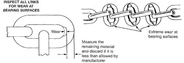
Minimum allowable thickness at any point on a link is as under.
| Nominal Chain or Coupling Link Size | Minimum Allowable Thickness at Any Point on The Link | ||
|---|---|---|---|
| Inch | mm | Inch | mm |
| 7/32 | 5.5 | 0.189 | 4.80 |
| 9/32 | 7 | 0.239 | 6.07 |
| 5/16 | 8 | 0.273 | 6.93 |
| 3/8 | 10 | 0.342 | 8.69 |
| 1/2 | 13 | 0.443 | 11.26 |
| 5/8 | 16 | 0.546 | 13.87 |
| 3/4 | 20 | 0.687 | 17.45 |
| 7/8 | 22 | 0.750 | 19.05 |
| 1 | 26 | 0.887 | 22.53 |
| 1 1/4 | 32 | 1.091 | 27.71 |
Note: Minimum allowable chain thickness is approximately 12 % reduction in diameter.
Use damaged slings only after they are repaired / reconditioned and proof tested by the sling manufacturer or a qualified person. Alloy steel chain, attachments, and coupling links used for repair shall conform to the strength requirements and other requirements of the original sling. It is recommended to replace rather than repair cracked, broken, or bent links.
Recommendations on Use of Chain Slings
Slings should be padded to prevent links from being bent and to protect the load.
Chain links and attachments shall hinge freely with adjacent links.
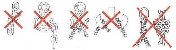
Chain slings shall not be shortened or lengthened by knotting, twisting, or other methods as shown below.
Go to Top
Synthetic Web Slings
Synthetic web slings are light and flexible. They are fabricated by sewing woven synthetic webbing of nylon or polyester (Dacron) yarns. They are often selected when expensive, highly polished, fragile or delicate loads are to be lifted. The softness of the web will not mar, deface or scratch loads, while its flexibility assures a firm, secure grip around the item being lifted. Web slings have the ability to elongate, absorbing and minimizing the effects of shock loads. Nylon is resistant to many alkalis where as polyester is resistant to many acids. Since they are non-sparking, they can be safely used in explosive atmospheres. Nylon slings are more common but polyester slings are often recommended where headroom is limited since they stretch only half as much as nylon slings. Synthetic web slings may be coated with suitable material to improve abrasion resistance, protection from sunlight or ultraviolet degradation, seal out moisture, and prevent grit from penetrating the web and causing internal wear.
Construction and Rated Loads
Slings can be fabricated from single or multiple plies, may include accessories such as edge guard, wear pads or sleeves, and are available in several configurations as under.

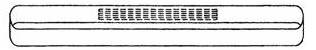
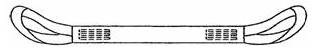
Type I
Sling made with a triangle fitting on one end and a slotted triangle choker fitting on the other end. It can be used in a vertical, basket, or choker hitch.

Type II
Sling made with a triangle fitting on both ends. It can be used in a vertical or basket hitch only.
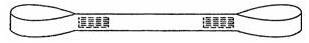
Type III
Sling made with flat loop eye on each end with loop eye opening on same plane as sling body. This type of sling is sometimes called a flat eye-and-eye, eye-and-eye, or double-eye sling.
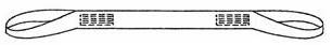
Type IV
Sling made with both loop eyes formed as in Type III, except that the loop eyes are turned to form a loop eye which is at a right angle to the plane of the sling body. This type of sling is commonly referred to as a twisted-eye sling.
Type V
Endless sling, sometimes referred to as a grommet. It is a continuous loop formed by joining the ends of the webbing together.
Type VI
Return-eye (reversed-eye) sling is formed by using multiple widths of webbing held edge-to-edge. A wear pad is attached on one or both sides of the sling body and on one or both sides of the loop eyes to form a loop eye at each end which is at a right angle to the plane of the sling body.
Synthetic web slings are made from two class of stuffer weave construction webbing with a minimum certified tensile strength per inch of width of the webbing as under.
Class 5 Webbing – 6800 pounds.
Class 7 Webbing – 9800 pounds.
Rated loads for Type I, II, III and IV single leg slings for vertical lift for various constructions are as under.
|
Width inch |
Rated Load in Pounds | ||||
|---|---|---|---|---|---|
|
One-ply Class 5 Webbing |
Two-ply Class 5 Webbing |
One-ply Class 7 Webbing |
Two-ply Class 7 Webbing |
Four-ply Class 7 Webbing |
|
| 1 | 1,100 | 2,200 | 1,600 | 3,100 | 5,500 |
| 1 1/2 | 1,600 | 3,300 | 2,300 | 4,700 | - |
| 1 3/4 | 1,900 | 3,800 | 2,700 | 5,400 | - |
| 2 | 2,200 | 4,400 | 3,100 | 6,200 | 11,000 |
| 3 | 3,300 | 6,600 | 4,700 | 8,800 | 16,450 |
| 4 | 4,400 | 8,200 | 6,200 | 11,000 | 20,400 |
| 5 | 5,500 | 10,200 | 7,800 | 13,700 | 25,500 |
| 6 | 6,600 | 12,300 | 9,300 | 16,500 | 30,600 |
Note: For Type VI slings, consult the manufacturer for rated loads
The rated capacity of synthetic web slings is based on the tensile strength of the webbing, a factor of safety of 5, and fabrication efficiency. Fabrication efficiency is typically 80 % to 85 % for single-ply slings but will be lower for multi-ply slings and very wide slings.
For slings made from other type of construction, select them based on rated load shown on sling identification.
Synthetic webbing materials other than nylon and polyester are also used and the manufacturer should be consulted for specific data for proper use.
Sling Attachments
If synthetic web slings incorporate metal fittings, the fittings shall have the following properties:
- Materials are compatible with the mechanical and environmental requirements of the sling.
- Fittings have a rated load at least the same as the synthetic webbing sling.
- They shall have sufficient strength to sustain twice the rated load of the sling without permanent deformation and a minimum breaking strength equal to five times the rated capacity of the sling.
- Surfaces shall be cleanly finished and sharp edges removed to prevent damage to the webbing.
To protect slings against wear and cutting due to repeated use against sharp corners, they are fitted with protective devices like buffer strips, edge guards and sleeve or sliding tube wear pads.
Effects of Environment
Certain synthetic materials perform better than others in specific applications and environments. Consult the sling manufacturer or a qualified person for a specific application or before using in and around chemical environments. High radiation or chemically active environments can destroy the strength of synthetic web slings. Specific environmental limits are as follows:
Do not use nylon and polyester slings in contact with objects or at temperatures in excess of 194º F (90º C), or below minus 40º F (minus 40º C).
Synthetic slings made from Kevlar (Kevlar is a registered trademark of DuPont de Nemours.), K-Spec (K-Spec is a registered trademark of SlingMax.) and nylon may be used in radiation areas when the responsible person ensures that the absorbed dose do not exceed 100,000 rad during the life of the sling.
Nylon web slings shall not be used where fumes, vapors, sprays, mists or liquids of acids are present.
Polyester web slings shall not be used where fumes, vapors, sprays, mists, or liquids of caustics are present.
Synthetic web slings are not recommended where extensive exposure to sunlight or ultraviolet light is experienced.
Store slings in an area where they will not be subjected to mechanical, chemical, or ultraviolet damage, or to extreme temperatures.
Inspection and Removal Criteria
Inspection should be made by the person handling the sling each day the sling is used. Periodic inspection shall be carried out at least annually by a qualified inspector.
Sling need replacement if cuts, holes, tears, broken stitching, worn eyes and worn or corroded or distorted fittings, burns from acid, caustics or heat are found.
Caution on Use of Synthetic Web Slings
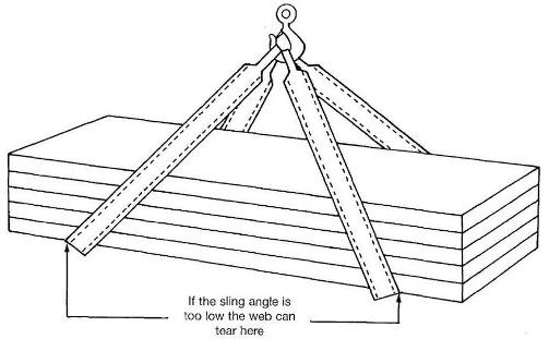
When using sling in bridle and basket configurations, they should be used with extreme caution. At low sling angles one edge of the web will be overloaded and the sling will tend to tear as shown below.
Go to Top
Synthetic Round Slings

Synthetic round slings also offer a number of advantages like synthetic web slings. They offer one additional advantage in that their jackets shield the fibre against ultraviolet degradation. A round sling is also easy to inspect and evaluate – if its jacket is damaged, take it out of service. Round slings have larger capacities than synthetic web slings of the same width. They can therefore be narrower.
Synthetic round slings are identified by Size Numbers adopted by the Web Sling and Tie Down Association to describe a slings or by Colour but always select them based on the vertical rated load shown on the sling identification.
Go to Top
Metal Mesh Slings
Metal mesh slings are widely used in metalworking and in other industries where loads are abrasive, hot, or will tend to cut web slings. Unlike nylon and wire rope slings, metal mesh slings resist abrasion and cutting. Metal mesh slings grip the load firmly without extensive stretching.
Construction and Rated Loads
Material for Fabric Construction: Carbon Steel.
| Fabric Construction | Heavy Duty | Medium Duty | Light Duty |
|---|---|---|---|
| Nominal spiral turns per foot mesh width | 35 | 43 | 59 |
| Approx. spiral wire size | 10 gage | 12 gage | 14 gage |
| Equivalent decimal size | 0.135 in. | 0.105 in. | 0.080 in. |
| Nominal cross rods per foot of fabric length | 21 | 30 | 38 |
| Approx. size of cross rods | 8 gage | 10 gage | 14 gage |
| Equivalent decimal size | 0.162 in. | 0.135 in. | 0.080 in. |
| Nominal fabric thickness | 1/2 in. | 3/8 in. | 5/16 in. |
Rated loads of Metal Mesh Slings based on Design Factor = 5 for vertical and choker lift are as under.
| Width inch | Rated Loads in Pounds (lbs) | ||
|---|---|---|---|
| Heavy Duty | Medium Duty | Light Duty | |
| 2 | 1,600 | 1,450 | 900 |
| 3 | 3,000 | 2,170 | 1,400 |
| 4 | 4,400 | 2,900 | 2,000 |
| 6 | 6,600 | 4,800 | 3,000 |
| 8 | 8,800 | 6,400 | 4,000 |
| 10 | 11,000 | 8,000 | 5,000 |
| 12 | 13,200 | 9,600 | 6,000 |
| 14 | 15,400 | 11,200 | 7,000 |
| 16 | 17,600 | 12,800 | 8,000 |
| 18 | 19,800 | 13,500 | 9,000 |
| 20 | 22,000 | 15,000 | 10,000 |
Metal mesh slings are also made from materials other than carbon steel. They are made from alloy steel for higher rated loads and stainless steel for corrosive environments.
Effect of Environment
Metal mesh slings can be used without a rated load reduction in temperatures ranging from minus 20º F (minus 29º C) to 550º F (288º C) except elastomer-coated slings. Use elastomer-coated slings in temperature ranges of 0º F (minus 18º C) to 200º F (93º C).
Inspection
Make periodic inspections of metal mesh slings at intervals not greater than 12 months. Look for following items.
- Broken wires in any part of the mesh.
- Broken weld or broken brazed joint along the sling edge.
- Reduction in wire diameter of 25 percent or more due to abrasion or 15 percent or more due to corrosion.
- Lack of flexibility due to distortion of the mesh.
- Pitted, corroded, cracked, bent, twisted, gouged, or broken fittings.
Go to Top
Natural and Synthetic Fibre Rope Slings
Slings manufactured from conventional three-strand natural or synthetic fiber rope are not recommended for use in lifting service. Natural or synthetic fiber rope slings shall be used only if other sling types are not suitable for the unique application.
Rated loads for synthetic fibre rope slings based on Design Factor = 5 and vertical lift are as under.
| Rope Diameter inch | Rated Loads for Vertical Lift in Pounds (lbs) | ||
|---|---|---|---|
| Nylon | Polyester | Polypropylene | |
| 1/2 | 1,100 | 1,000 | 760 |
| 9/16 | 1,400 | 1,300 | 920 |
| 5/8 | 1,800 | 1,600 | 1,100 |
| 3/4 | 2,600 | 2,200 | 1,500 |
| 7/8 | 3,500 | 3,000 | 2,100 |
| 1 | 4,400 | 4,000 | 2,600 |
| 1 1/8 | 5,700 | 5,000 | 3,200 |
| 1 1/4 | 7,000 | 6,000 | 3,900 |
| 1 5/16 | 7,700 | 6,500 | 4,200 |
| 1 1/2 | 9,700 | 8,400 | 5,500 |
| 1 5/8 | 11,500 | 9,900 | 6,400 |
| 1 3/4 | 13,200 | 11,400 | 7,400 |
| 2 | 16,900 | 14,400 | 9,400 |
| 2 1/8 | 19,100 | 16,200 | 10,500 |
| 2 1/4 | 21,400 | 18,100 | 11,900 |
| 2 1/2 | 26,300 | 22,000 | 14,400 |
| 2 5/8 | 28,800 | 24,200 | 16,100 |
| 3 | 37,100 | 31,200 | 20,500 |
D/d ratio for rope slings shall be larger than 8/1.
Go to Top
General Recommendations on Use of Slings
All types of slings shall have, as a minimum, the rated capacity clearly and permanently marked on each sling.
Each sling shall receive a documented inspection at least annually, more frequently if recommended by the manufacturer or made necessary by service conditions.
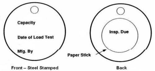
Wire rope slings shall be labeled with a tag or other identification methods similar to one shown below.
When repaired, a sling shall be permanently marked to identify the repairing agency.
New and repaired / reconditioned slings including welded components shall be proof load tested by the sling manufacturer or repair agency.
Replace hooks that have been opened more than 15% of the normal throat opening measured at the narrowest point or twisted more than 10° from the plane of the unbent hook.
Ensure that in a choker hitch, the choke point is only on the sling body, never on a fitting.
Do not rest loads on the sling. Do not pull a sling from under a load when the load is resting on the sling.
Do not drag slings on the floor or over abrasive surfaces.
For more information on slings please refer ANSI/ASME B30.9.
Go to Top
Acknowledgement:
In this article some information is taken from OSHA’s website.
Their website address is – http://www.osha.gov/dsg/guidance/slings.
