When sufficient load is applied to a material, it will cause the material to change shape. This change in shape is called deformation. A temporary shape change that is self-reversing after the force is removed, so that the object returns to its original shape, is called elastic deformation. In other words, elastic deformation is a change in shape of a material at low stress that is recoverable after the stress is removed. This type of deformation involves stretching of the bonds (but the atoms do not slip past each other or twin which requires breaking of bonds).
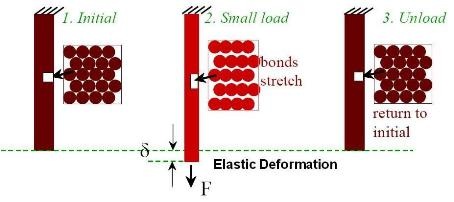
Above figure schematically shows elastic deformation.
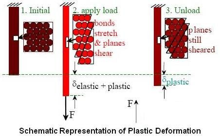
When the stress is sufficient to permanently deform the metal, it is called plastic deformation. Plastic deformation involves the breaking and remaking of atomic bonds. Plastic deformation may take place by slip, twinning or a combination of both methods.
Fracture is the separation of a single body into pieces by an imposed stress. Information about plastic deformation and fracture is given in this article.
Deformation by Slip
As polycrystalline material is made up of many grains which may have second phase particles and grain boundaries. It is therefore easier to study plastic deformation in a single crystal to eliminate the effects of grain boundaries and second phase particles. Much information regarding the mechanism of plastic deformation may be obtained by studying the behavior of a single crystal under stress and later applying this knowledge to a polycrystalline material.
If a single crystal of a metal is stressed in tension beyond its elastic limit, it elongates slightly, a step appears on the surface indicating relative displacement of one part of the crystal with respect to the rest, and the elongation stops. Increasing the load will cause movement on another parallel plane, resulting in another step. It is as if neighboring thin sections of the crystal had slipped past one another like sliding cards on a deck. Each successive elongation requires a higher stress and results in the appearance of another step. With progressive increase of the load, a stage is reached which causes the material to fracture.
Investigations showed that sliding occurred in certain planes of atoms in the crystal and along certain directions in these planes. Thus the mechanism is a new type of flow. It is a flow that depends upon the perfectly repetitive structure of the crystal which allows the atoms in one face of a slip plane to shear away from their original neighbors in the other face, to slid in an organized way along this face carrying their own half of the crystal with them, and finally to join up again with a new set of neighbors as nearly perfect as before. The movement in the crystal takes place along planes having highest atomic density with greatest distance between similar parallel planes and in the direction of close-packed atoms.
This can be simply stated as: Slip occurs on planes that have highest planer density of atoms and in the direction with highest linear density of atoms.
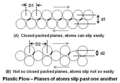
Slip occurs in directions in which the atoms are most closely packed since this requires the least amount of energy. As shown in above figure, close-packed rows are vertically further apart from each other (d1) than rows that are not close-packed (d2), therefore they can slip past each other with less interference. Black bars between atoms show the slop of the path of atoms. Since the slop is less steep in case of closed-packed rows, less force is required for a given horizontal displacement. In addition, less displacement (D1 < D2) is required by the atoms to move from one stable position (before slip) to other stable position (after slip).
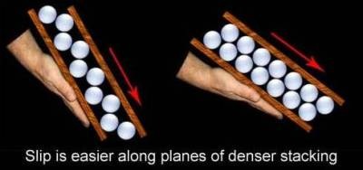
To get a better grasp of this, think of gluing ping pong balls to two boards in a widely spaced pattern as shown in above figure. Put the boards together, ping pong balls to ping pong balls, and begin to tilt the bottom board. You will have to go to a very steep angle before the top board will slip from its position of the nestled ping pong balls. Now do the experiment again, but this time gluing the balls very close together. The top board will now slip at a much lesser angle.
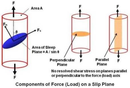
Investigation of the orientation of the slip plane with respect to the applied load indicates that slip takes place as a result of simple shearing stress. Resolution of axial tensile load F in above figure gives two loads. One is shear load (Fs = F cosθ) along the slip plane and the other a normal tensile load (Fn = F sinθ) perpendicular to the plane. The area of the slip plane is A/sinθ, where A is the cross sectional area perpendicular to F. The resulting shear stress (Ss) is,
Ss = (F cosθ)/(A/sinθ) = (F/A) cosθ sinθ = (F/2A) sin2θ
It can be seen from the equation that shear stress (Ss) will be maximum when θ = 45°.
If slip planes are either parallel or perpendicular to the direction of applied load, slip cannot occur, and either the material deforms by twinning or it fractures.
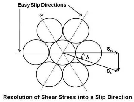
Above figure shows the packing of atoms on a slip plane. There are three directions in which the atoms are close-packed, and these would be the easy slip directions. The shear stress Ss, on the slip plane, which was derived earlier, may not coincide with one of these easy slip directions and has to be resolved into the nearest slip direction to determine the resolved shear stress Srs. As the diagram shows, the stress is related by the cosine of the angle λ, and the resolved shear stress is,
Ssr = (F/2A) sin2θ cosλ
Investigation has shown that differently oriented crystals of a given metal will begin to slip when different axial stresses are applied but that the critical resolved shear stress, that is, the stress required to initiate slip, is always the same.
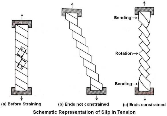
As deformation proceeds and the tensile load remains axial, both the plane of slip and the direction of slip tend to rotate into the axis of rotation as shown above.
(One can imagine a single crystal as a deck of cards. If the deck is pushed straight down, it will be unchanged. But if it is just pushed on the side at an angle, it will deform and rotate in the direction of push).
Mechanism of Slip
Note:
In following text, to show negative sign, a BAR (¯) is placed before a character instead of placing it above the character since it is not possible to place a BAR above a character in typing.
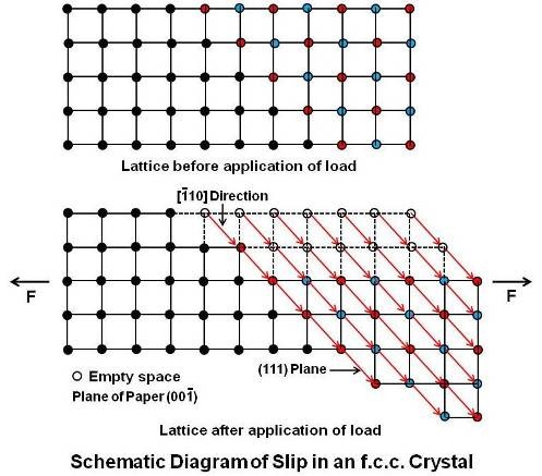
In slip as explained above, portions of the crystal on either side of a specific slip plane move in opposite directions and come to rest with the atoms in nearly equilibrium positions, so that there is very little change in the lattice orientation. Thus the external shape of the crystal is changed without destroying it. Schematically, slip in an f.c.c. (face centered cubic) lattice is explained below.
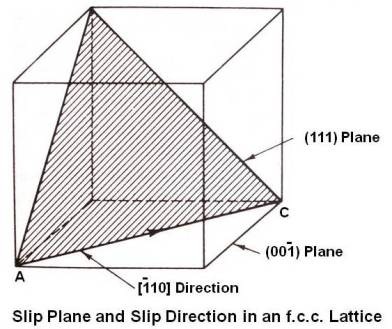
Above figure shows slip plane and slip direction in an f.c.c. lattice. The (111) plane is the slip plane having maximum number of atoms (densest plane). It intersects the (00¯1) plane in the line AC, [¯110] direction having maximum number of atoms on it.
When the (00¯1) plane is assumed to be the plane of paper and many unit cells are taken together, slip is seen as a movement along the (111) planes in the close packed [¯110] direction, a distance of one lattice dimension or multiple of that dimension as under.
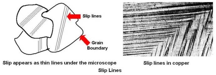
The series of steps formed will generally appear under the microscope as a group of approximately parallel lines as shown below. Slip lines in a copper specimen are also shown.
From the schematic diagram of slip in an f.c.c. crystal shown above, one may assume that the motion consists of a simultaneous movement of planes of atoms across each other. However, a more reasonable assumption is that the atoms slip consecutively, starting at one place or at a few places in the slip plane, and then move outward over the rest of the plane.
Sir Neville Mott has linked slip to the sliding of a large heavy rug across a floor as shown below.

If one tries to slide the entire rug as one piece, the resistance is too much. What one can do is to make a wrinkle in the rug and then slide the whole rug a little at a time by pushing the wrinkle along. A similar analogy to the wrinkle in the rug is the movement of an earthworm. It advances in a direction by advancing a part of its body at a time.
As shown below, similar thing happens in slip.
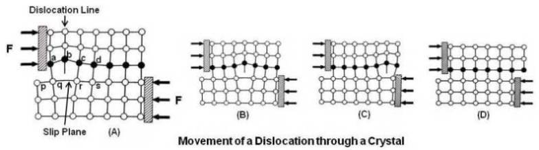
By application of the shear force, first an extra plane of atoms (called a dislocation) forms above the slip plane. In above figure, p q r s is the slip plane. On application of force, bond between atoms a & p and b & q breaks and creates a new bond between atoms at a & q and a dislocation at b as shown at (A). On continued application of force, this dislocation advances by breaking old bonds and making new bonds. In the next move, bond between atoms at c and r is broken and a new bond is made between atoms at b and r, resulting in a dislocation at c. Thus the dislocation moved from b to c. Thus, this dislocation moves across the slip plane and leaves a step when it comes out at the surface of the crystal as shown at (D). Each time the dislocation moves across the slip plane, the crystal moves one atom spacing.
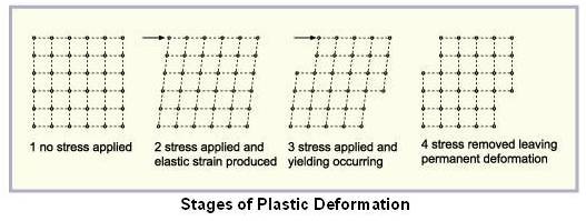
Above figure schematically shows various stages of plastic deformation when stress is applied.
Since the atoms do not end up in exactly normal positions after the passage of the dislocation, subsequent movement of the dislocation across the same slip plane encounters great resistance. Further deformation will require movement on another slip plane. Although the distortion is greatest on the active slip plane, its effect is felt throughout the lattice structure, and the applied load must be increased to cause movement on another slip plane.
It is observed that the experimentally observed value of critical resolved shear stress is quite low as compared to the theoretically calculated value as dislocations already exist in the crystal structure as a result of imperfections (defects) in the crystal structure during solidification. It is therefore not necessary to create a dislocation, but simply to start an existing one moving on the slip plane.
Deformation by Twinning
In certain materials, particularly c.h.p. metals, twinning is a major means of deformation. Twinning is a movement of planes of atoms in the lattice parallel to a specific (twinning) plane. In twinning the atoms move only a fraction of an interatomic space and this leads to a change of the lattice structure in the twined region. The amount of movement of each plane of atoms in the twinned region is proportional to its distance from the twinning plane. Schematically, twinning in an f.c.c. (face centered cubic) lattice is explained below.
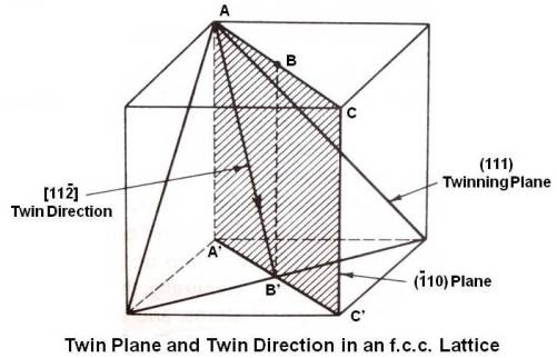
In above figure, (111) plane is the twinning plane. It intersects the (¯110) plane along the line AB’. Thus the twin direction is [11¯2]. The mechanism of twinning is shown below.
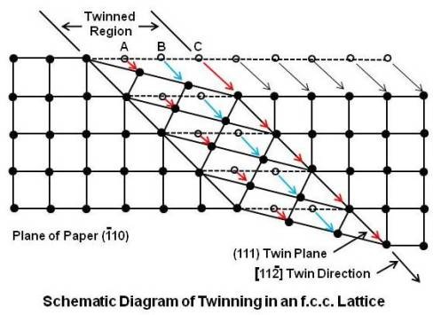
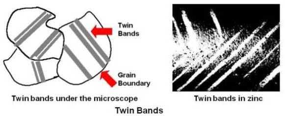
The plane of paper is the (¯110) plane along the line AB’ and many unit cells are taken together. Each (111) plane (plane at A, at B, at C and so on) in the twinned region moves in shear in the [11¯2] direction. The first one at A moves one-third of an interatomic distance. The second one at B moves two-third of an interatomic distance. The third one at C moves an entire spacing. There is a change in lattice structure in the twinned region as the atoms end up in interatomic spaces. The twined region separates/divides the crystal into two regions oriented in such a way that one forms a mirror image of the other relative to the twin plane between them. Generally, the twinned region appears microscopically as a broad line or band as shown below. Twin bands in a zinc specimen are also shown.
Two kinds of twins are of interest to the metallurgists:
Deformation or mechanical twins, most prevalent in c.p.h. metals (magnesium, zinc) and b.c.c. metals (tungsten, α iron, etc.) and
Annealing twins, most prevalent in f.c.c. metals (aluminum, copper, brass, etc.). These metals have been previously worked and heat treated. The twins are formed because of a change in the normal growth mechanism.
Slip vs. Twinning
The difference between slip and twinning is as under.
| Item | Slip | Twinning |
|---|---|---|
| Atomic movement | Atoms move a whole number of atomic spacing. | Atoms move fractional atomic spacing. |
| Microscopic appearance | Thin lines | Wide bands or broad lines |
| Lattice orientation | No change in lattice orientation. The steps are only visible on the surface of the crystal and can be removed by polishing. After polishing there is no evidence of slip. | Lattice orientation changes. Surface polishing will not destroy the evidence of twinning. |
Fracture
Fracture is the separation of a single body into pieces by an imposed stress. For engineering materials there are only two possible modes of fracture, ductile and brittle. In general, the main difference between brittle and ductile fracture can be attributed to the amount of plastic deformation that the material undergoes before fracture occurs. Ductile materials show large amounts of plastic deformation while brittle materials show little or no plastic deformation before fracture.
Brittle fracture generally involves rapid propagation of a crack with minimum energy absorption and plastic deformation. In single crystals, brittle fracture occurs by cleavage as the result of tensile stress acting normal to crystallographic planes with low bonding (cleavage planes), creating smooth surfaces (a flat crystal face). In polycrystalline materials, the brittle fracture surface shows a granular appearance because of the changes in orientation of the cleavage planes from grain to grain.
In amorphous solids, the lack of a crystalline structure results in a conchoidal fracture with cracks proceeding normal to the applied tensile stress. When material breaks without following any natural planes of separation, it is called a conchoidal fracture.
As with plastic deformation, the difference between the theoretical fracture strength and the actual fracture strength is due to structural irregularities. The first explanation of this discrepancy was given by Griffith in 1921. He theorized that failure in brittle materials was caused by many fine elliptical, submicroscopic cracks in the metal. The sharpness at the tip of such cracks results in very high stress concentration which may exceed the theoretical fracture strength at this localized area and cause the crack to propagate.
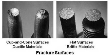
Crack initiation and propagation are essential to fracture. In brittle materials cracks spread very rapidly. Once they are initiated, they will continue to grow and increase in magnitude till fracture. Fractured surfaces of ductile and brittle materials are shown below.
It is possible that microcracks may exist in the metal due to the previous history of solidification or working. However, even an initially sound material may develop cracks on an atomic scale. A mechanism of crack formation is shown below.
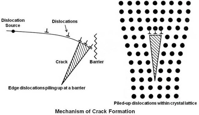
As shown in above figure, the pile-up of dislocations at a barrier which might be of grain boundary or included particle may result in a microcrack. Within crystal lattice microcracks are created when three unit dislocations combine into a single dislocation.
From above explanation, it is apparent that any method that will increase the mobility of dislocations will tend to reduce the possibility of brittle fracture.
Ductile fracture occurs after considerable plastic deformation prior to failure and the crack moves slowly. The crack will usually not extend unless an increased stress is applied. The failure of most polycrystalline ductile materials occurs with a cup-and-cone fracture associated with the formation of a neck in a tensile specimen. In ductile material the fracture begins by the formation of cavities (microvoids) in the center of the necked region. In most commercial metals, these internal cavities probably form at nonmetallic inclusions. This belief is supported by the fact that extremely pure metals are much more ductile than those of slightly lower purity. Under continued applies stress, the cavities grow and coalesce to form a crack in the center of the sample. The crack proceeds outward toward the surface of the sample in a direction perpendicular to the applied stress. Completion of the fracture occurs vary rapidly along a surface that makes an angle of approximately 45° with the tensile axis. The final stage leaves a circular lip on one half of the sample and a bevel on the surface of the other half. Thus one half has the appearance of a shallow cup, and the other half resembles a cone with a flattened top, giving rise to the term cup-and-cone fracture.
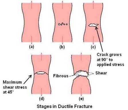
Various stages during ductile fracture are schematically shown in above figure.
(a) Necking
(b) Cavity formation
(c) Cavity coalescence to form a crack
(d) Crack propagation
(e) Fracture
On both macroscopic and microscopic levels, ductile fracture surfaces have distinct features. Macroscopically, ductile fracture surfaces have larger necking regions and an overall rougher appearance than a brittle fracture surface. Figure given below shows the macroscopic differences between two ductile specimens and one brittle specimen.
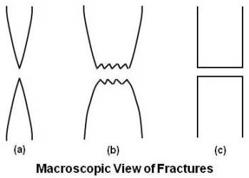
(a) Highly ductile fracture in which the specimen necks down to a point
(b) Moderately ductile fracture after some necking
(c) Brittle specimen without any plastic deformation
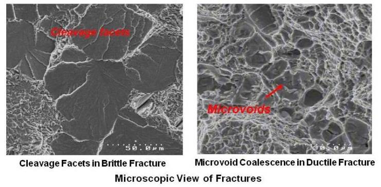
On the microscopic level also, ductile fracture surfaces appear rough and irregular. The surface consists of many microvoids and dimples. Microscopic view of brittle and ductile fractured surfaces is shown in figure given below.
Slip, Twinning and Fracture
The amount of deformation that can occur before fracture is determined by the relative values of the stresses required for slip, twinning and cleavage. There is a critical resolved shear stress for slip which is increased by alloying, decreasing temperature and prior deformation. There is a critical resolved shear stress for twinning which is also increased by prior deformation. There is also a critical normal stress for cleavage on a particular plane which is not sensitive to prior deformation and temperature. When a stress is applied to a crystal, which process takes place depends upon which critical stress is exceeded first. If the critical resolved sear stress for slip or twinning is reached first, the crystal will slip or twin and show some ductility. If, however, the critical normal stress is reached first, the crystal will cleavage along the plane concerned with little or no plastic deformation.
In most design situations a material that demonstrates ductile fracture is usually preferred for several reasons. First and foremost, brittle fracture occurs very rapidly and catastrophically without any warning. Ductile materials plastically deform, thereby slowing the process of fracture and giving ample time for the problem to be corrected. Secondly, as the ductile material deforms more and more, its strength and hardness increase because of the generation of more and more dislocations and more stress is needed to cause ductile fracture.
Polycrystalline Material
The preceding discussion described plastic deformation in single crystals. However, commercial material is always made up of many grains (called polycrystalline), whose crystal axes are oriented at random. When polycrystalline material is subjected to stress, slip starts first in those grains in which the slip system is most favorably situated with respect to the applied stress. Since contact at the grain boundaries must be maintained, it may be necessary for more than one slip system to operate. The rotation into the axis of tension brings other grains, originally less favorably oriented, into a position where they can now deform. As deformation and rotation proceed, the individual grains tend to elongate in the direction of flow.
All work done in deformation is not dissipated in heat. Part of it is stored in the crystal as an increase in internal energy. Since the crystal axes of adjacent grains are randomly oriented, the slip planes and twinning planes must change direction in going from grain to grain. This can be seen in figures of slip lines and twin bands showing different direction for slip lines and twin bands in adjacent grains. This means that more work is done at the grain boundaries and more internal energy will exist at those points.
When a crystal deforms, there is some distortion of the lattice structure. This deformation is greatest on the slip planes and grain boundaries and increases with increasing deformation. This is evident by an increase in resistance to further deformation. The material is undergoing strain hardening or work hardening. In addition to distortion of the lattice structure, the pile up of dislocations against obstacles (grain boundaries, foreign atoms, etc.) and locking of dislocations on intersecting slip planes increase the resistance to further deformation.
Since dislocations pile up at grain boundaries, metals can, to some extent, be hardened by reducing the size of the grains. Alloying introduces foreign atoms that distort the crystal locally around themselves, and these local distortions offer resistance to the movement of a nearby dislocation.
One shall remember that whenever there is distortion of the lattice structure, whether it is a result of plastic deformation, heat treatment or alloying, there will be an increase in the strength and hardness of the material.
Effect of Cold Working on Properties
Work (strain) hardening is a phenomenon which results in an increase in hardness and strength of a metal subject to plastic deformation (cold working) at temperatures lower than the recrystallization range.
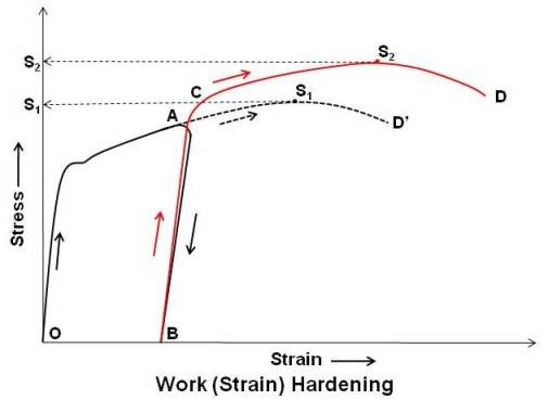
As shown in above figure, when a specimen is loaded, the strain increases with stress and the curve reaches the point A in the plastic range. If at this stage, the specimen is unloaded, the strain does not recover along the original path AO, but moves along AB. If the specimen is again loaded, the strain increases with stress from B to A but via another path (the slop of stress strain line is steeper indicating that the material has got harder than before) and reaches the point C, and follows the curvature if loading is continued.
If the specimen would not have been unloaded after point A, the stress strain curve would have followed the dotted path AD’. Comparison of path AD’ and ACD show that the due to cold working, yield strength and ultimate strength have increased. Ultimate strength increased from S1 to S2.
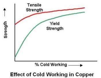
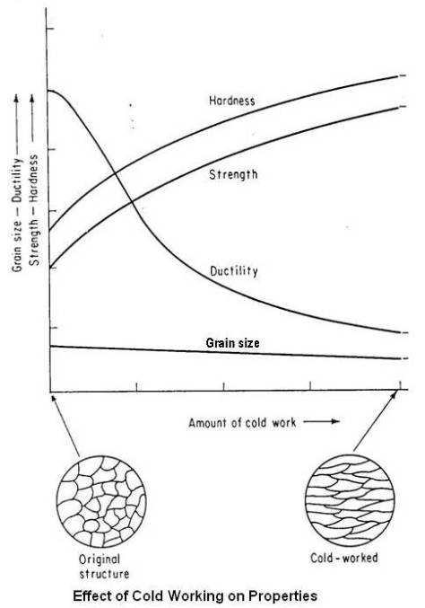
A material is considered to be cold worked if its grains are in a distorted condition after plastic deformation is completed. All the properties of a metal that are dependent on the lattice structure are affected by plastic deformation or cold working. Tensile strength, yield strength and hardness increases, while ductility decreases. Effect of cold working on tensile and yield strength of copper is shown in figure given below.
Although both strength and hardness increase, the rate of change is not the same. Hardness generally increases most rapidly in the first 10 percent reduction (cold work), whereas the tensile strength increases more or less linearly. The yield strength increases more rapidly than the tensile strength, so that, as the amount of plastic deformation is increased, the gap between the yield and tensile strengths decreases. This is important in certain forming operations where appreciable deformation is required. In drawing, for example, the load must be above the yield point to obtain appreciable deformation but below the tensile strength to avoid failure. If the gap is narrow, very close control of the load is required. Ductility follows a path opposite to that of hardness. A large decrease in the first 10 percent reduction and then a decrease at a slower rate as shown in the figure given below.
Distortion of the lattice structure hinders the passage of electrons and decreases electrical conductivity. This effect is small in pure metals but is appreciable in alloys.
To illustrate effect of plastic deformation on tensile properties, effect of cold rolling in 70:30 brass is given below.
| Reduction by Cold Rolling, % |
Tensile Strength (psi) | Elongation (% in 2 inch) |
Rockwell Hardness (1/16 inch ball indenter, 75 kg load) |
|---|---|---|---|
| 0 | 43,000 | 70 | 12 |
| 10 | 48,000 | 52 | 62 |
| 20 | 53,000 | 35 | 83 |
| 30 | 60,000 | 20 | 89 |
| 40 | 70,900 | 12 | 94 |
| 50 | 80,000 | 8 | 97 |
| 60 | 90,000 | 6 | 100 |
The increase in internal energy, particularly at the grain boundaries, makes the material more susceptible to inter granular corrosion, thereby reducing its corrosion resistance. Known as stress corrosion, this is an acceleration of corrosion in certain environments due to residual stresses resulting from cold working. One of the ways to avoid stress corrosion cracking is to relieve the internal stresses by suitable heat treatment after cold working and before placing the material in service.
It may be noted that strain hardening leads to an anisotropy that is only beneficial, from a strengthening standpoint, in an orientation parallel to the direction of cold working. The opposite applies to the properties in a direction perpendicular to that working. In order to get properties in all directions (i.e., isotropy), a stress-relieving operation will most likely be necessary to re-obtain the grain uniformity.
Transition between Ductile and Brittle Fractures
In fracture, there are many shades of gray. Brittle fracture and ductile fracture are fairly general terms describing the two opposite extremes of the fracture spectrum. A material lean toward one type of fracture as opposed to the other type depending on many factors. Three of them are as under.
Temperature
The first and foremost factor is temperature. Basically, at higher temperatures the yield strength is lowered and the fracture is more ductile in nature. On the opposite end, at lower temperatures the yield strength is greater and the fracture is more brittle in nature. This relationship with temperature has to do with atom vibrations. As temperature increases, the atoms in the material vibrate with greater frequency and amplitude. This increased vibration allows the atoms under stress to slip to new places in the material (i.e. break bonds and form new ones with other atoms in the material). This slippage of atoms is seen on the outside of the material as plastic deformation, a common feature of ductile fracture.
When temperature decreases however, the exact opposite is true. Atom vibration decreases, and the atoms do not want to slip to new locations in the material. So when the stress on the material becomes high enough, the atoms just break their bonds and do not form new ones. This decrease in slippage causes little plastic deformation before fracture. Thus, we have a brittle type fracture.
At moderate temperatures (with respect to the material) the material exhibits characteristics of both types of fracture. In conclusion, temperature determines the amount of brittle or ductile fracture that can occur in a material.
Dislocation Density
Another factor that determines the amount of brittle or ductile fracture that occurs in a material is dislocation density. The higher the dislocation density, the more brittle the fracture will be in the material (for example, due to cold working). The idea behind this theory is that plastic deformation comes from the movement of dislocations. As dislocations increase in a material due to stresses above the materials yield point, it becomes increasingly difficult for the dislocations to move because they pile into each other. So a material that already has a high dislocation density can deform less before it fractures resulting in a brittle type of fracture.
Grain Size
The last factor is grain size. As grains get smaller in a material, the fracture becomes more brittle. This phenomenon is due to the fact that in smaller grains, dislocations have less space to move before they hit a grain boundary. When dislocations can not move very far before fracture, then plastic deformation decreases. Thus, the material’s fracture is more brittle.
