In as quenched martensite condition, the steel is too brittle for any application. It is so brittle that even slight impacts may cause fracture. The formation of martensite also leaves high residual stresses in the steel. Therefore, hardening is almost always followed by tempering. Tempering is a heat treatment that reduces the brittleness of a steel without significantly lowering its hardness and strength. Information about tempering of steel is given in this article.
Tempering
For tempering, steel is heated to some temperature below the lower critical temperature (Ae1 / Ac1). The purpose of tempering is to relieve residual stresses and to improve the ductility and toughness of the steel. This increase in ductility is usually attained at the sacrifice of the hardness or strength.
In general, over the broad range of tempering temperatures, hardness decreases and toughness increases as the tempering temperature is increased. This is true if the toughness is measured by reduction of area in a tensile test. However, this is not entirely true if the notched bar such as Izod or Charpy test is used as a measure of toughness. Most steels actually show a decrease in notched-bar toughness when tempered between 400 and 800°F, even though the piece at the same time looses hardness and strength. The reason for this decrease in toughness is not fully understood. The figure given below shows typical variation of hardness and notched-bar toughness with tempering temperature for plain-carbon and low-alloy steels.
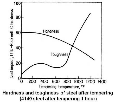
The tempering range of 400 to 800°F is a dividing line between applications that require high hardness and those requiring high toughness. For hardness or wear resistance, the part is tempered below 400°F and for toughness it is tempered above 800°F. However, if the part does not have any “stress risers†or notches, the change in ductility may be a better indication of toughness than the notched-bar test, the tempering in the range 400 to 800°F may not be detrimental.
Residual stress is relieved to a large extent when the tempering temperature reaches 400°F and by 900°F it is almost completely gone.
Martensite is a supersaturated solid solution of carbon trapped in a body-centered tetragonal structure. This is a metastable condition and as energy is applied by tempering, the carbon precipitate as carbide and the iron changes to body centered cubic lattice. There will be diffusion and coalescence of the carbide as the tempering temperature is raised.
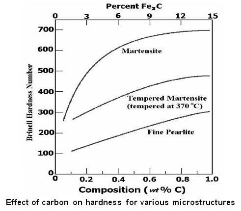
Hardness of martensite depends on carbon content of steel. Its hardness is low if the carbon content of the steel is low, and high if the carbon content of the steel exceeds 0.4%C.The figure given below shows effect of carbon content on hardness for various microstructure of steel.
When plain carbon steel is heated in the range of 100 to 400°F, the structure etches dark and is sometimes known as black martensite. The original as-quenched martensite is beginning to lose its tetragonal crystal structure by the formation of a hexagonal closed-packed transition carbide (epsilon carbide) and low-carbon martensite.
Heating in the range from 450 to 750°F changes the epsilon carbide to orthorhombic cementite (Fe3C), the low-carbon martensite becomes b.c.c. ferrite and any retained austenite is transformed to lower bainite. The carbides are too small to be resolved by optical microscope and the entire structure etches rapidly to a black mass formerly called troostite.
Tempering in the range of 750 to 1200°F continues the growth of the cementite particles. This coalescence of the carbide particles allows more of the ferrite matrix to be seen, causing the sample to etch lighter than the low-temperature product. This structure was formerly known as sorbite.
Hearting in the range from 1200 to 1333°F produces large, globular cementite particles. This structure is very soft and tough and is similar to the spheroidized cementite structure obtained directly from austenite by a spheroidized annealing.
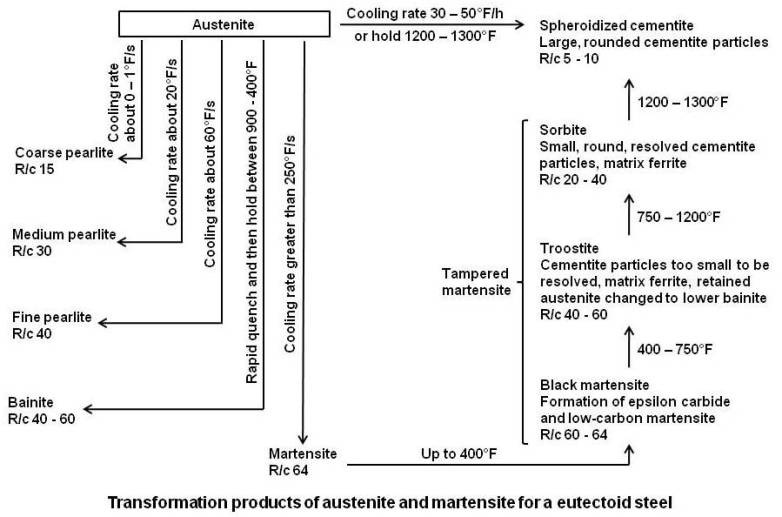
In past, tempering process was divided into definite stages and the microstructure appearing in these stages was given names like troostite and sorbite. However, the changes in microstructure are gradual and hence the product of tempering at any temperature is called tempered martensite. The transformation products of austenite and martensite are summarized in the figure given below.
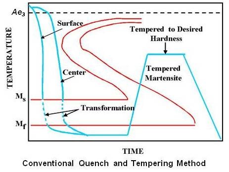
Since tempering is a process which involves energy, both time and temperature need to be considered. The same effect can be achieved by using a shorter time at higher temperature or by using a longer time at a lower temperature. Schematic transformation diagram for conventional quench and temper method is shown in the figure given below.
Important Question
If a medium tensile strength is required, one may ask why it is necessary first to form a fully martensite structure and then to reduce the strength substantially in tempering, when the same tensile strength may be obtained, with less difficulty in quenching, from mixtures of martensite and bainite or martensite and pearlite.
The answer lies in the following experiment.
Samples of a medium-carbon alloy steel were heat treated in three different ways as under.
- Quenched to martensite.
- Partially transformed isothermally to bainite and quenched to form a mixture of bainite and martensite.
- Partially transformed isothermally to ferrite and pearlite and then quenched, resulting in a mixture of largely pearlite and martensite.
The three samples were then tempered to the same tensile strength of 125000 psi and tested.
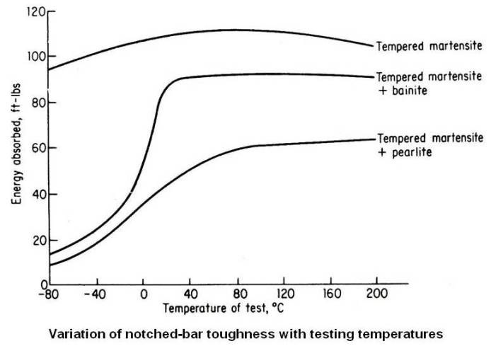
The sample that was fully martensite before tempering had the highest yield strength, the highest ductility, the highest fatigue strength and the greatest toughness. The figure given below shows the notched-bar toughness of the three structures at different testing temperatures. The results are self explanatory.
Austempering
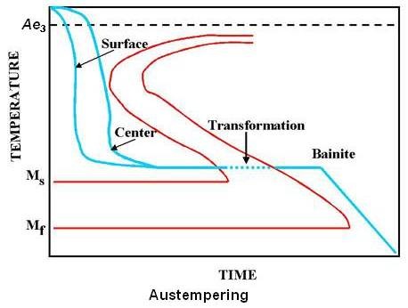
Austempering is a heat treatment process developed from the I-T diagram to obtain a structure which is 100 percent bainite. It is accomplished by first heating the part to the required austenitizing temperature followed by cooling rapidly in a salt bath held in the bainite range (usually between 400 and 800°F). The piece is left in the bath until the transformation to bainite is complete. The steel directly gets transformed to bainite from austenite. At no time it is in the fully hardened martensite state. Austempering is a complete heat treatment process and no reheating is required as in tempering. Schematic transformation diagram for austempering is shown in the figure given below.
The comparison of mechanical properties developed (at the same hardness or strength) by austempering and conventional quench and tempered methods is made in the table given below.
| Property | Quenched and Tempered | Austempering |
|---|---|---|
| Rockwell C hardness | 49.8 | 50.0 |
| Ultimate tensile strength, psi | 259000 | 259000 |
| Elongation, % in 2 in. | 3.75 | 5.0 |
| Reduction in area, % | 26.1 | 46.4 |
| Impact, ft-lb (unnotched round specimen) | 14.0 | 36.6 |
| Free bend test | Ruptured at 45° | Greater than 150° without rupture |
The superiority of austempering shows up in properties like reduction of area in tension, resistance to impact and the free bend test. The marked improvement in the impact strength of austempered parts is most pronounced in the hardness range of Rockwell C 45 to 55. In addition to this, in austempering, there is also less distortion and danger of quenching cracks because the quenching is not as drastic as in the conventional quenching method.
The main limitation of austempering is the effect of mass of the part being heat treated. Only sections which can be cooled fast enough to avoid transformation to pearlite, in the range of 900 to 1200°F, are suitable. Therefore, most industrial applications have been in sections less than ½ in. thick.
Residual Stresses
These are the stresses that remain in the part after the force has disappeared. Residual stresses always arise from a nonuniform plastic deformation. In case of heat treatment, this nonuniform plastic deformation may be caused by the temperature gradient or the phase change or usually a combination of both factors during cooling. Residual stresses are a very serious problem in heat treatment, since they often result in distortion or cracking and in some cases in premature failure of the part in service.
The following will give some insight into and appreciation of the factors that give rise to these stresses.
During quenching, the surface is cooled more rapidly than the inside. This results in a temperature gradient across the cross section of the piece or a temperature difference between the surface and the center. Since the outside and inside are attached to each other, the inside being hotter is longer (Almost all solids expand as they are heated and contract as they are cooled), will prevent the outside from contracting as much as it should. It will therefore elongate the outside layers, putting them in tension while the inside in turn will be in compression. In case the tensile stress exceeds the ultimate tensile strength of the material, cracking will occur. This is what usually happens when glass is subjected to a large temperature difference. In case of steel, however, thermal stresses alone very rarely lead to cracking. If stress is below the yield strength of the steel, the stress will be borne elastically. When the entire piece has reached room temperature, and therefore, since the thermal stress will be zero, there will be no distortion. If the stress exceeds the yield strength, the surface layer will be plastically deform or permanently elongated. At room temperature the surface will have residual compressive stress and the inside, residual tensile stress. If the piece was originally cylindrical, it will now be barrel-shaped.
Austenite being f.c.c. (face-centered cubic), is a denser structure than any of its transformation products. Therefore, when austenite changes to ferrite, pearlite, bainite or martensite, an expansion occurs. The austenite-to-martensite expansion is the largest and amounts to a volume increase of about 4.6 percent. The martensite expansion will be greater the lower the Ms temperature.
In situation when the tensile crack is internal and cannot come to the surface due to the compressive stress in the surface layers, it will not get detected. X-ray testing or in some cases Magnaflux inspection may show the presence of internal fissures. Many times the part is placed in to service without knowledge of the internal quenching cracks. As soon as there is the slightest bit of tensile stress in the surface due to external load, the crack will come through and the part will fail.
As the problem of residual stresses is quite complex, combined effect of above factors is not discussed here.
Martempering or Marquenching
We have seen that in austempering, there is less distortion and danger of quenching cracks because the quenching is not as drastic as in the conventional quenching method. Another very effective method of minimizing distortion and cracking is by martempering.
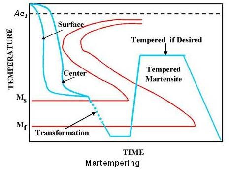
Martempering is carried out by heating to the proper austenitizing temperature, quenching rapidly in a liquid-salt bath held just above the Ms temperature, and holding for a period of time. This allows the surface and the center to reach the same temperature. Air cooling to room temperature then follows. Since air cooling from just above the martensite-formation range introduces very little temperature gradient, the martensite will be formed at nearly the same time throughout the piece. Thus martempering minimizes residual stresses and greatly reduces the danger of distortion and cracking. The heat treatment is completed by tempering the martensite to the desired hardness. Schematic transformation diagram for martempering is shown in the figure given below.
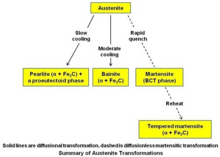
The block diagram given below gives summary of austenite transformation.