The ability of a mechanical seal to meet its performance objectives depends upon a wide range of factors involving equipment design, operating conditions and selection of the type of seal and the material of construction. As information on equipment design (types of mechanical seals, methods of environment control and equipment parameters) and operating conditions (Start-up procedure) are covered in an article on Mechanical Seal – Practical Information, information about selection of type of mechanical seal and material of construction is given in this article.
Selection of Type of Mechanical Seal
Single Seal
The design, arrangement and material selection of a seal is basically determined by pressure, temperature, speed of rotation and characteristics of the pumped medium. Shaft diameters of 5 To 500 mm, pressures from 10 torr (vacuum) to 250 bar, temperatures from -200°C to +450°C and sliding velocities up to 150 m/s limit the operating range of mechanical seals. Type of a mechanical seal for various parameters may be selected as under.
| Temperatures | Single Seal Type | |||
|---|---|---|---|---|
| Inside | Outside | |||
| Unbalanced | Balanced | Unbalanced | Balanced | |
| Up to 120 ºC | √ | √ | √ | √ |
| 120º C – 205 ºC | √ | √ | √ | |
| Over 205 ºC | √ | |||
| Pressures | Single Seal Type | |||
|---|---|---|---|---|
| Inside | Outside | |||
| Unbalanced | Balanced | Unbalanced | Balanced | |
| Up to 10 Kg/Cm2 | √ | √ | √ | √ |
| 10 to 35 Kg/Cm2 | √ | √ | ||
| Over 35 Kg/Cm2 | √ | |||
| Speeds | Single Seal Type | |||
|---|---|---|---|---|
| Inside | Outside | |||
| Unbalanced | Balanced | Unbalanced | Balanced | |
| Up to 7.6 m/s | √ | √ | √ | √ |
| 7.6 to 15.2 m/s | √ | √ | √ | |
| Over 15.2 m/s | √ | |||
m/s = meters per second
Double Seal
Double seal arrangement with additional seal supply systems or buffer fluid systems may be required depending on the quality of the medium (toxic, inflammable, crystallizing, corrosive, abrasives in fluid, etc).
Material of Construction
Seal components can be divided into three major categories – seal faces, secondary sealing elements and metal components.
Seal Faces
The rotating and stationary sealing faces commonly referred to as primary seal members are the most important components of a mechanical seal. They shall be selected based on their compatibility with the fluid being pumped. Following materials are widely used as seal face material.
Resin Impregnated Carbon
This is the normal rotary seal face material recommended in most general purpose application involving corrosive fluids. This carbon exhibits good resistance to thermal shock and good dimensional stability over a wide temperature range. It has also low permeability and good thermal conductivity.
Metal Impregnated Hard Carbon
This is an antimony impregnated hard carbon that is specially suited for extreme heavy duty application involving non-corrosive media. Boiler feed water and hydrocarbon service seals with hard carbon as a mating face have a much longer service life. Hard carbon exhibits better abrasive resistance and emergency dry running characteristics.
Ceramic
This is a super fine grain high Alumina ceramic material (99.5 % Al2O3) that exhibits excellent low wear characteristics. It is the best seal face material for highly corrosive chemical services. 95.0 % purity material may be used for light duty application.
Tungsten Carbide
This is universally accepted hard seal face material. It is available in two forms – nickel bonded and cobalt bonded. Solid seal rings are offered as a standard as against shrunk-fit faces with their inherent limitations.
Silicon Carbide
Technologically this is the best seal face material available to date. It is available in two varieties, reaction bonded and sintered. It is highly resistant to thermal stress and corrosion in high temperature oxidizing atmospheres. It has low wear properties and is an idle seal face material for most of sealing applications. Silicon carbide also exhibits better dry run capabilities making it an ideal choice for critical duties in the nuclear and thermal power industries.
Glass filled PTFE
It is offered as a standard seal face material on outside mounted PTFE bellows type seals. It is recommended for corrosive applications. Safe working temperature rang for PTFE is -200 to 260° C.
Other Materials
Alternate face materials are available for custom seals and other special applications. Seal faces of stainless steel with stelliting and Ni-resist are available. Cast iron faces are also available for certain non-critical applications.
Note:
Carbon face is made in many grades and is priced from the cheap / mass-produced grades to expensive metal-powder impregnated varieties. While ordering spare carbon ring from local supplier, specify correct grade of carbon for your application.
Properties of various face materials are as under.
| Material | Density gram/cm3 | Thermal Conductivity W/mºC | Hardness | Max. Temp. Limit, ºC |
|---|---|---|---|---|
| Carbon, resin impregnated | 1.83 | 6 | 100 BHN | 275 |
| Carbon, antimony impregnated | 2.15 | 8 | 115 BHN | 350 |
| Tungsten Carbide Solid (6% Co) | 15 | 100 | 1500 Vickers | 400 |
| Silicon Carbide | 3.1 | 145 | 2400 Vickers | 1650 |
| Alumina Oxide (99.5 %) | 3.9 | 35 | 1800 Vickers | 175 |
Seal Pressure – Velocity Limitations
Seal faces require cooling and lubrication to function properly. The hydraulic pressure acting on the seal faces and the rotating speed of the rotary seal will generate heat. This heat limits seal design and material. The PV – (face pressure x velocity) capability of two opposing material is indicative of an ability to sustain a fluid film for long operational life. Typical PV – Limits of face material combinations in non-lubricating fluids, i.e. watery substances are as under.
| Primary (rotating) Ring | Mating (stationary) Ring | PV Limit (bar x m/s) |
|---|---|---|
| Glass-Filled PTFE | Ceramic / Silicon Carbide | 61.3 |
| Carbon | Cast Iron | 245.2 |
| Carbon | Ceramic | 245.2 |
| Carbon | Tungsten Carbide | 1225.9 |
| Carbon | Silicon Carbide | 1471.1 |
| Tungsten Carbide | Tungsten Carbide | 249.2 |
| Silicon Carbide | Silicon Carbide | 858.1 |
Note: For lubricating fluids multiply number by 1.5.
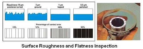
Seal Face Surface Finish and Seal Face Flatness
To maintain a healthy lubricating fluid film between seal faces they are lapped to make them flat and smooth. If faces are not flat, waviness will generate hydrodynamic lifting force on seal faces as we try to compress non-compressible liquid trapped between the lapped faces. Seal surfaces shall be smooth also to reduce friction between them by increasing contact area.
There is often confusion between the terms "Seal face flatness" and "Seal face surface finish". Seal face surface finish addresses the subject of roughness, and is measured in terms of "rms" (root mean square) or CLA (center line average). One of the ways to measure roughness is by comparing our sample to standards that have been polished to different degrees of roughness. Flatness is a different term that describes a level surface that has no elevations or depressions. We use term waviness to describe this condition when we refer to mechanical seal faces. It is this flatness that is of the most concern. One can read the flatness by using an optical flat and a monochromatic light source as explained below.
Flatness is measured by using light characteristic – that when two lights of the same wave length interfere with each other, the light disappears and the reflecting piece goes black. A monochromatic or single wave length light source (mono means one, and chromatic means color).) is used for this. Most companies use a pink color that comes off a helium gas light source. This color has a wave length of just about 0.6 microns (0.000023 inches). To measure flatness, an optical flat (a precision ground and polished clear glass of optical quality) is placed on the piece to be measured. The monochromatic light is aimed at the piece and this light reflects off of the piece back through the optical flat causing interference light bands. If the distance between the optical flat and the piece we are measuring is one half the wave length of helium, or an even multiple of the number, the band will show black. This is referred to as a helium light band and because it is one half the wave length of helium it measures 0.3 microns or 0.0000116 inches. Flatness is checked by comparing the pattern we see with a chart supplied by the measuring equipment manufacturer.
Flatness of lapped faces should be within following light bands:
Carbon and GFT: 2 to 3 light bands.
TC, SiC and Ceramic: 1 to 2 light bands.
For high pressure application (> 40 bar), faces should be lapped within 1 light band.
Carbon graphite faces relax after lapping. Although lapped to less than one light band by the seal manufacturer, you will see readings as high as three light bands if you check the faces. These faces should return to flat once they are placed against a hard face that is flat.
Seals that are going to be used in cryogenic (cold) service should be lapped at the cryogenic temperature.
Finished faces shall have following average surface finish:
Tungsten Carbide: 0.01 µm
Silicon Carbide: 0.04 µm
Hard Carbon: 0.1 µm
Ceramic: 0.07 µm
Hydrodynamic Grooves.
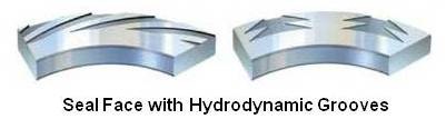
Sometimes hydrodynamic grooves are provided on hard face as shown above for effective lubrication between faces.
Secondary Sealing Elements
Secondary seals perform the function of sealing between mechanical seal elements as well as sealing the mechanical seal and the equipment. They are either static or dynamic type in the form of O-rings, wedges, bellows and gaskets.
For information on gaskets used for sealing seal and the equipment, please refer an article on gaskets. Bellows and wedges are made from PTFE. Bellows are also made from elastomers and metal. O-rings are made from elastomers.
Elastomers
To be classified as a true elastomer you should be able to compress an O-ring and have it return to 90% of its original shape in less than five seconds after the compression force is removed. It is this elasticity that gives the compound its memory and eliminates the need for external loading to seal. If the compound does not return to 90% of its original shape in five seconds or less it is called a "plastic" material and becomes less desirable as a dynamic seal in mechanical seal design. Most of Perfluoroelastomers are plastics. Generally one of the following elastomer materials is used to make an O-ring.
- Butyl
- Buna N
- Neoprene
- Ethylene propylene
- Fluorocarbons: They are sold by manufacturers under their style / produce number. Dupont E60 Viton ®, 3M Fluorel 2174, Parker 747-75 and Parker V884-85 are typical examples.
- Perfluoroelastomers: Chemraz (a registered trademark of Greene, Tweed & Co.) or Kalrez ® (a registered trademark of Dupont, USA) are typical examples. They are used for high temperature and aggressive chemical applications. Their chemical resistance is often compared with PTFE. They are very expensive compounds.
The O-ring selected must be chemically compatible with fluid to be handled. It is very common to clean and flush process lines with a solvent or steam. The O-ring selected must be chemically compatible with them also. Most of the chemicals can be handled by either fluorocarbon (Viton/ Fluorel) or Ethylene Propylene. Ethylene Propylene is easily attacked by any petroleum product so be careful with the type of lubricant you use to lubricate it. For all practical purposes silicone grease is probably the safest lubricant but to be sure check for its compatibility.
Each of these elastomers has an upper and lower temperature limit. Although the elastomer may be chemically compatible with the sealing fluid it could still fail if the temperature limit is exceeded. Safe temperature range for various elastomers is as under.
| Elastomer | Temperature Range °C |
|---|---|
| Butyl | -40 to 130 |
| Buna N (Nitrile) | -40 to 105 |
| Neoprene | -40 to 120 |
| Ethylene propylene | -40 to 150 |
| Flurocarbon (Viton ®) | -20 to 200 |
| Chemraz | -30 to 205 |
| Kalrez ® (many grades are available) | -20 to (218 to 315 based on type of grade). |
Note:
Elastomers are poor conductors of heat. Cooling one side of the O-ring does not always allow the coolant to conduct to the hot side.
Most of the o-ring compounds are available in a wide range of durometer or hardness. The average mechanical seal uses a durometer of 75 to 80 (as measured on the shore A scale), but harder durometers are available for high pressure applications.
One measures o-ring sizes by the inside diameter (D) and the cross section diameter (d). O-rings are the most precision rubber part that one can purchase. They are manufactured to a tolerance of ± 0.08 mm.
The maximum volume of the o-ring should never be more than the minimum volume of the gland groove. The groove depth must be less than the o-ring cross-section and the groove width must be larger than the o-ring cross-section.
Identification of O-ring Material by Burning Test (destructive test)
To identify Viton, Burn Test may be carried out. When ignited, Neoprene and Ethylene propylene burns with a flame where as Viton does not burn with a flame.
Metal Components
Metal is used for making mechanical seal hardware. This hardware, depending on seal design can include sleeves, retaining rings, set screws, pins, springs, bellows and glands. Although mechanical seal have some unique requirements, the material selection generally does not differ much from material selection for the equipment. As seal components are thinner than equipment components, materials offering best corrosion resistance are selected for hardware. Many of the common names used for material designation are actually trade marks of the material manufacturer. Following material are widely used for making mechanical seal hardware.
Stainless Steel 316
AISI 316 (UNS S31600) is considered the base material for most seal designs. It should not be used in service with high chlorides since it is susceptible to pitting corrosion.
Alloy C-276
Alloy C-276 (UNS N10276) is one of the most widely used high alloy material used for aggressive environments. It is used for all major seal components including sleeves, glands and fasteners. C-276 is a nickel-molybedenum-chromium alloy. It is used as standard alloy for springs and is defined as the default spring material in API 682 (2004).
Alloy 20
Alloy 20 (UNS N08020) is a nickel-chromium-molybdenum alloy. It was originally developed for hot sulfuric acid application. It is used for applications that cause stress corrosion cracking.
Alloy 400
Alloy 400 (UNS N04400) is a copper-nickel alloy that exhibit good corrosion resistance against many chemicals. It is used for sea water, sulfuric acid, hydrochloric acid, hydrofluoric acid and alkalies.
Alloy K 500
Monel alloy K 500 (UNS N05500) is used for components requiring high strength like set screws and fasteners.
Alloy 350
Alloy 350 (UNS S35000) is a chromium-nickel-molybdenum alloy that exhibit high strength in high temperature applications. It is mainly used for making bellows.
Alloy 718
Alloy 718 (UNS N07718).is a nickel-chromium alloy that exhibits excellent corrosion resistance and high temperature properties. The material is mainly used for making welded metal bellows. This alloy has been adopted as the default material for Type C seals in API 682 (2004).
Note:
UNS stands for Unified numbering system.
For more information on mechanical seal material selection please refer API Standard 682, 2004 –“Pumps-Shaft Sealing Systems for Centrifugal and Rotary Pumps”.
Acknowledgment:
Information about metal components in this article is briefly reproduced from Proceedings of the Twenty Second International Pump Users Symposium 2005.
