A fastener is a device that holds two or more objects together. A fastener can be a bolt and nut, a screw, a rivet, or even a staple. However, the majority of fasteners used in industry are threaded fasteners. They are used to join individual elements in a secure and cheap way that can be assembled & disassembled as often as required. Information about thread terminology, types of threads, fits and tolerance, designation method, manufacturing operations for threaded fasteners and useful information for threaded fasteners is given in this article.
Click on a link below to jump to a topic or read all.
Thread Terminology
Types of Threads
Thread Size Comparison
Fits and Tolerances
Designation Method
Manufacturing Operations for Threaded Fasteners
Useful Information for Threaded Fasteners
Thread Terminology
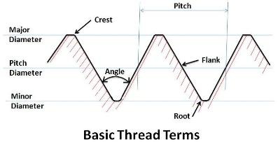
Sketch showing basic thread terms and meaning of commonly used thread terms and fasteners are as under.
Screw Thread
A screw thread is a raised helical ridge of constant section around the interior or exterior of a cylindrically shaped object.
Screw
A headed threaded fastener that is designed to be used in conjunction with a pre formed internal thread or alternatively forming its own thread (Historically, it was a threaded fastener with the thread running up to the head of the fastener that has no plain shank).
Bolt
A bolt is the term used for a threaded fastener, with a head, designed to be used in conjunction with a nut. Obviously a standard ‘bolt’ can be used in a tapped hole or with a nut.
Stud
A fastener which is threaded at both ends with an unthreaded shank in between. One end (which often has a thread tolerance which results in more thread interference) is secured into a tapped hole, the other is used with a nut.
Thread Crest
The crest of a thread is the prominent part of a thread. For external threads, the crest is the region of the thread which is on its outer surface, for internal threads it is the region which forms the inner diameter.
Thread Root
The thread root is the bottom of the groove between the two flanking surfaces of the thread.
Thread Flanks
The thread flanks are the straight sides that join the crest and root.
Included Angle
The angle created by two adjacent flanks.
Pitch
The pitch of a thread is the distance, measured parallel to its axis, between corresponding points on adjacent surfaces, in the same axial plane. It is expressed in threads per inch (tpi) or as an absolute dimension for one single pitch (i.e. 1mm, 0.75mm etc.).
Pitch Point
The position on the thread where an equal amount of distance exists between the flanks on the solid part of the thread and in the space between the threads.
Pitch Diameter
The measured distance between the pitch points between the threads.
Major Diameter
The diameter of the imaginary co-axial cylinder that just touches the crest of an external thread or the root of an internal thread. Major diameter is the largest diameter on a threaded part. It is also known as nominal or thread diameter.
Minor Diameter
It is the diameter of an imaginary co-axial cylinder that just touches the roots of an external thread or the crests of an internal thread. Minor diameter is the smallest diameter on a thread part. It is also known as root diameter.
Thread Height
This is the distance between the minor and major diameters of the thread measured radially.
Shank
The portion of a bolt between the head and the threaded portion.
Thread Runout
The portion at the end of a threaded shank which is not cut or rolled to full depth, but which provides a transition between full depth threads and the fastener shank or head.
Start
The number of individual threads on a device. Multi-start threads have basically the single start form, but with the pitch based on number of starts. For example, a double start thread has doubled pitch.
Lead
The distance that a screw travels in one revolution.
Thread Form
The shape or profile of a thread. like “V” shape, square shape, etc. A major part of any thread is the crest & root form. Usually but not always this takes the form of a radius. Some times a flat. A 100% sharp "V" is undesirable as it may form the stress point for fracture and on external threads it can cut fingers.
Go to Top
Types of Threads
Threads were developed in many parts of the world, and as such produced an array of different standards. Proposal of Joseph Whitworth having 55 degree V thread form and standard threads per inch for various diameters (based on sample screws from a large number of British workshops) in 1841 became standard practice in Britain in the 1860′s. In 1864 in America, William Sellers independently proposed another standard based upon a 60 degree V thread form and various thread pitches for different diameters. Subsequently it developed into the American Standard Coarse Series (NC) and the Fine Series (NF). The thread form had flat roots and crests that made the screw easier to make than the Whitworth standard that has rounded roots and crests. Around the same time metric thread standards were being adopted in continental Europe. The standard international metric thread eventually evolved from German and French metric standards based upon a 60 degree V thread with flat crests and rounded roots.
The most common screw thread form is a symmetrical V-Profile. The included angle is 60 degrees. This form is prevalent in the Unified Screw Thread (UNC, UNF) form as well as the ISO Metric thread. Information on various types of threads is as under.
British Standard Whitworth (BSW)
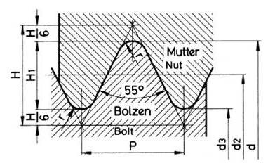
This thread form was developed by Sir Joseph Whitworth. This was the first standardized thread form. The thread form is specified in BS 84: 1956. It has a symmetrical V-Profile. The angle between the thread flanks is 55 degrees and the thread has radii at both the roots and the crests of the thread.
P = Pitch = 1/Number of threads per inch (tpi)
H = Depth = 0.960491 x P
H/6 = Shortening at crest and roots = 0.160083 x P
H1 = Actual depth of thread = 0.640327 x P
r = Radius at the Crest & Root = 0.137329 x P
d = Major Diameter
d2 = Effective or Pitch Diameter
d3 = Minor Diameter
British Standard Fine (BSF)
The British Standard Fine (BSF) thread has the same profile as the BSW thread form but was used when a finer pitch was required for a given diameter (more threads per inch for a given diameter). This thread form was first introduced in 1908. The thread form is specified in BS 84: 1956.
British Association (BA)
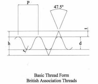
This thread was used for small diameter threads (below 0.25 inches diameter). The thread has radiused roots and crests and has a flank angle of 47.5 degrees. The thread size varies from BA number 23 (0.33 mm diameter with a pitch of 0.09 mm) to BA number 0 (6mm diameter with a pitch of 1 mm). The thread form is now redundant and has been replaced by Unified and Metric threads.
P = Pitch = 1/Number of threads per inch (tpi)
h = Height = 1.1363365 x P
d = Actual Depth = 0.60000 x P
t = Shortening = 0.2681688 x P
r = Radius at the Crest & Root = 0.1808346 x P
ISO Metric and Unified Threads
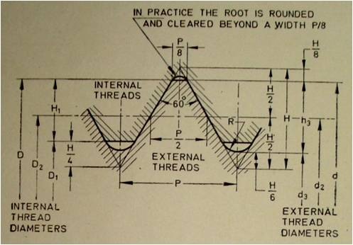
Basic thread form for ISO Metric and Unified Threads is as shown below.
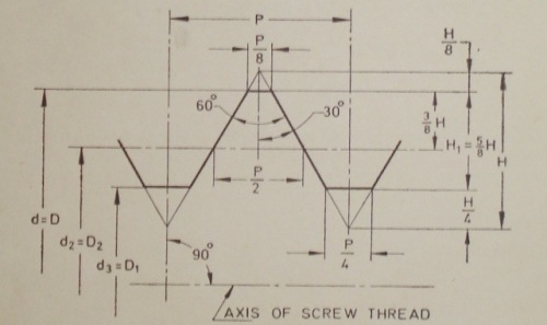
The thread form for ISO Metric (Coarse and Fine) and Unified threads (UNC, UNF and UNEF) are identical.
P = Pitch = 1/Number of threads per inch (tpi)
H = Depth (height of fundamental triangle) = 0.866025 x P
H/8 = Shortening of major diameter = 0.108253 x P
H/4 = Shortening of minor diameter = 0.216506 x P
H1 = 5/8 H = Actual depth of thread = 0.541266 x P
R = Radius at the Root = 0.14434 x P (for ISO external thread)
D, d = Major diameter of internal and external thread
D2, d2 = Pitch diameter of internal and external thread
D1, d1 = Minor diameter of internal and external thread
Design Profiles of ISO Metric External and Internal Threads
The design profiles of external and internal threads in maximum material condition are as under. These are the profiles to which the deviations are applied to define the limits of sizes.
D, d = Major diameter of internal and external thread
D2 = d2 = d – ¾ H = d – 0.64952P
D1 = d2 – 2 (H/2 – H/4) = d – 2H1 = d – 1.08253P
d3 = d2 – 2 (H/2 – H/6) = d – 1.22687P
H1 = (D – D1) / 2 = 5H/8 = 0.54127P
h3 = (d – d3) / 2 = 17H/24 = 0.61343P and
R = H/6 = 0.14434P
h3 = Basic depth of external threads
To provide resistance to fatigue and shock loads, the roots of the external and internal threads shall be rounded off within the limiting profile as shown in above sketch.
Metric threads are designated by the letter M followed by the nominal major diameter of the thread and the pitch in millimeters. For example M10 x 1.25 indicates that the major diameter of the thread is 10 mm and the pitch is 1.25 mm (fine thread). The absence of a pitch value indicates that a coarse thread is specified. For example stating that a thread is M10 indicates a coarse thread series is specified of diameter 10 mm (giving the thread a pitch of 1.5mm).
In November 1948 the Unified thread was agreed upon by the UK, the US and Canada to be used as the single standard for all countries using inch units. It was standardized unifying the Whitworth and American standard thread forms.
In 1965 the British Standards Institution issued a policy statement requesting that organizations should regard the BSW, BSF and BA threads as obsolescent. The first choice replacement for future designs was to be the ISO metric thread with the ISO inch (Unified) thread being the second choice.
Unified thread sizes (specific combinations of diameter and pitch) are identified by the letter combination "UN" in the thread symbol. In the unified standards, the pitch diameter tolerances for external threads differ from those for internal threads; for this reason the letter "A" is used in the thread symbol to denote an external thread and the letter "B" an internal thread. Where the letters "U", "A" or "B" do not appear in the thread designation, the threads conform to the outdated American National screw threads.
Unified (UN/UNR) and its predecessor, American National screw threads, have substantially the same thread form, and threads of both standards having the same diameter and pitch are mechanically interchangeable. The principal differences between these standards relate to the application of allowances, the variation of tolerances with size, differences in the amounts of pitch diameter tolerances for external and internal threads, and differences in thread designations.
Unified inch and ISO metric screw threads are not mechanically interchangeable.
UNR applies only to external threads; the difference between UN and UNR threads, in addition to designation, is that a flat or optional rounded root contour is specified for UN threads, while only a rounded root contour is specified for UNR threads. The majority of fasteners with a Unified thread form have a rounded root contour.
Screw Thread Series
The Metric ISO thread series consists of two series with specific pitches (coarse and fine threads). For some size of fasteners, fine series have more than one specified pitch.
Inch fasteners are available in standard series and eight series with constant pitches. The standard series consists of three series with graded pitches (coarse, fine, and extra–fine) designated as UNC, UNF and UNEF. The eight series with constant pitches have 4, 6, 8, 12, 16, 20, 28, or 32 threads per inch.
Thread Selection – Coarse / Fine / Extra-Fine
Coarse Thread
The coarse thread is generally used for the bulk production of screws, bolts, and nuts. It is commonly used in relatively low strength materials. Coarse threads provide more resistance to internal thread stripping than the fine or extra-fine series. Coarse threads are advantageous where rapid assembly or disassembly is required, or if corrosion or damage from nicks due to handling or use is likely.
Fine Thread
The fine thread is commonly used for bolts and nuts in high strength applications. They have less thread depth and a larger minor diameter than coarse threads. Consequently more strength is available to external threads than for coarse threads of the same nominal size. In order to prevent internal thread stripping, a longer length of engagement is required for fine series than for coarse series threads for thread materials of the same strength levels. Fine threads have less tendency to loosen under vibration than coarse series threads. They also allows for finer adjustment in assembly.
Extra-fine threads
The extra-fine threads are used particularly for equipment and threaded parts that require very fine adjustment, such as bearing retaining nuts, adjusting screws, etc.
At times fasteners with constant thread pitch series are used instead of standard series as under.
8-UN series
A standard diameter-pitch combination with 8 threads per inch. This series is commonly used instead of UNC threads for bolt diameters over 1 inch.
12-UN series
A standard diameter-pitch combination with 12 threads per inch. This series is commonly used instead of UNF threads for bolt diameters over 1 1/2 inch.
16-UN series
A standard diameter-pitch combination with 16 threads per inch. This series is also used for fine threads with bolt diameters over 1 3/4 inch.
Go to Top
Thread Size Comparison
For ready reference – comparison of various types of threads in size range 3.00 mm to 42.00 is as under.
| METRIC PRODUCTS | UNIFIED INCH PRODUCTS | B.S. INCH PRODUCTS | ||||||||||||||||||||||||||||||||||||||
|---|---|---|---|---|---|---|---|---|---|---|---|---|---|---|---|---|---|---|---|---|---|---|---|---|---|---|---|---|---|---|---|---|---|---|---|---|---|---|---|---|
| SIZE | THREAD PITCH & T.P.I |
|
|
|
|
|
|
|
|
|
||||||||||||||||||||||||||||||
|
||||||||||||||||||||||||||||||||||||||||
| PITCH (MM) | TPI | PITCH (MM) | TPI | mm | Inch | UNC | UNF | BSW | BSF | BA | ||||||||||||||||||||||||||||||
| M3 | 0.50 | 51 | – | – | 3.00 | 0.118 | #5 | 40 | 44 | 0.125 | 1/8 | 40 | – | 0.125 | ||||||||||||||||||||||||||
| #6 |
32 |
40 |
0.138 |
5 BA 4 BA |
43.1 38.5 |
0.126 0.142 |
||||||||||||||||||||||||||||||||||
| M4 M5 |
0.70 0.80 |
36 32 |
– – |
– – |
4.00 5.00 |
0.157 0.197 |
#8 #10 |
32 24 |
36 32 |
0.164 0.190 |
3 BA 3/16 |
24 |
32 |
0.187 |
34.8 |
0.161 |
||||||||||||||||||||||||
| 2 BA 1 BA |
31.3 28.2 |
0.185 0.209 |
||||||||||||||||||||||||||||||||||||||
| M6 |
1.0 |
1.25 |
– |
– |
6.00 |
0.236 |
1/4 |
20 |
28 |
0.250 |
1/4 0 BA |
20 |
26 |
0.250 |
25.4 |
0.236 |
||||||||||||||||||||||||
| M8 M10 |
1.25 1.50 |
20 17 |
1.00 1.25 |
25 20 |
8.00 10.00 |
0.315 0.394 |
5/16 3/8 |
18 16 |
24 24 |
0.313 0.375 |
5/16 3/8 |
18 16 |
20 22 |
0.313 0.375 |
||||||||||||||||||||||||||
| M12 | 1.75 | 14.5 | 1.25 | 20 | 12.00 | 0.472 | 1/2 | 13 | 20 | 0.50 | 7/16 1/2 |
14 12 |
18 16 |
0.438 0.500 |
||||||||||||||||||||||||||
| M14 M16 |
2.00 2.00 |
12.5 12.5 |
1.50 1.50 |
17 17 |
14.00 16.00 |
0.551 0.630 |
5/8 | 11 | 18 | 0.625 | 5/8 | 11 | 14 | 0.625 | ||||||||||||||||||||||||||
| (M18) M20 (M22) |
2.50 2.50 2.50 |
10 10 10 |
1.50 1.50 1.50 |
17 17 17 |
18.00 20.00 22.00 |
0.709 0.787 0.866 |
3/4 7/8 |
10 9 |
16 14 |
0.750 0.875 |
3/4 7/8 |
10 9 |
12 11 |
0.750 0.875 |
||||||||||||||||||||||||||
| M24 |
3.00 |
8.5 |
2.00 |
13 |
24.00 |
0.945 |
1 1-1/8 |
8 7 |
12 12 |
1.000 1.125 |
1 1-1/8 |
8 7 |
10 9 |
1.000 1.125 |
||||||||||||||||||||||||||
| (M27) M30 |
3.00 3.50 |
8.50 7.25 |
2.00 2.00 |
13 13 |
27.00 30.00 |
1.063 1.181 |
1-1/4 | 7 | 12 | 1.250 | 1-1/4 | 7 | 9 | 1.250 | ||||||||||||||||||||||||||
| (M33) M36 |
3.50 4.00 |
7.25 6.40 |
2.00 3.00 |
13 8.5 |
33.00 36.00 |
1.299 1.417 |
1-1/2 |
6 |
12 |
1.500 |
1-1/2 |
6 |
8 |
1.500 |
||||||||||||||||||||||||||
| (M39) M42 |
4.00 4.50 |
6.40 5.60 |
3.00 3.00 |
8.5 8.5 |
39.00 42.00 |
1.535 1.653 |
||||||||||||||||||||||||||||||||||
|
||||||||||||||||||||||||||||||||||||||||
Go to Top
Fits and Tolerances
The basic profile is the theoretical profile of the thread. To ensure that a bolt thread can be screwed into a nut thread, actual profiles of both the nut and bolt threads must never cross the theoretical profile. For this actual profile of bolt threads shall be always equal to, or smaller than, the dimensions of the basic profile. Nut threads shall always be equal to or greater than the basic profile. To ensure this in practice, tolerances and allowances are applied to the basic profile.
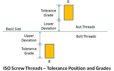
Usually nut threads have a tolerance applied to the basic profile such that it is theoretically possible for the nut thread profile to be equal to the theoretical profile (by selecting Lower Deviation = Zero). Bolt threads usually have a gap between the basic and actual thread profiles. This gap is called the fundamental deviation (shown as Upper Deviation and Lower Deviation in above sketch) with metric threads and the allowance with inch-based threads. The tolerance is subsequently applied to the thread.
Fundamental Deviation
An intentional clearance between internal or external thread and the design form (basic size) of the thread when the thread is on its maximum metal condition. For metric threads the fundamental deviation are designated by capital letters (G, H, etc.) for internal threads and small letters (g, h, etc.) for external threads.
Fundamental deviation is the distance of the tolerance position from the basic size of the thread profile. For nut threads there are two tolerance positions, H with a zero fundamental deviation and G with a positive fundamental deviation. For bolt threads there are four tolerance positions. Position h has a zero fundamental deviation. Positions e, f, and g have negative fundamental deviations.
Tolerance Grade
The difference between maximum and minimum metal conditions for a tolerance applied to a screw thread. For metric threads the tolerance grade is given by a number. Lower the number, smaller the tolerance.
Tolerance Class
A combination of tolerance grade and a fundamental deviation which is given to an internal or external thread. A tolerance class for an internal thread when combined with the tolerance class for an external thread gives the class of fit for the mating threads.
Class of Fit
The Class of Fit is a measure of the degree of fit between mating internal and external threads. It is a system that designates in general how loose or tight the threads should be. There are three main Classes of Fit for metric screw threads as under.
Fine:
This has a tolerance class of 5H for internal threads and 4h for external threads.
Medium:
This has a tolerance class of 6H for internal threads and 6g for external threads.
The standard tolerance classes of 6g for the bolt thread and 6H for the nut thread are typically included on a drawing as default. The standard tolerance classes apply strictly only when a relatively short length of engagement is used (such as with a nut which is typically 0.8d where d is the thread size).
Coarse:
This has a tolerance class of 7H for internal threads and 8g for external threads.
For Unified threads, a similar designation as for metric threads is used. External threads or bolts are designated with the suffix "A" and internal or nut threads with "B". The thread classes used are 1A, 2A and 3A for external threads and 1B, 2B and 3B for internal threads. The different thread classes have differing amounts of tolerance and allowance. Allowance is specified only for Classes 1A and 2A and the allowance is identical for both classes. Tolerance decreases as class number increases (e.g., tolerance for Class 3A is less than that for Class 2A, which is less than that for Class 1A).
Classes of Fit for unified screw threads are as under.
Classes 1A and 1B:
For work of rough commercial quality where loose fit is acceptable. They are used in military for conditions where parts may need to be assembled quickly even with dirty or slightly damaged threads.
Classes 2A and 2B:
The recognized standard for normal production of the great bulk of commercial bolts, nuts and screws.
Classes 3A and 3B:
Used where a closed fit between mating parts for high quality work is required. Normally they are used for aerospace applications.
Class 4:
A theoretical rather than practical class, now obsolete.
Class 5:
For a wrench fit. Used principally for studs and their mating tapped holes. A force fit requiring the application of high torque for semi-permanent assembly.
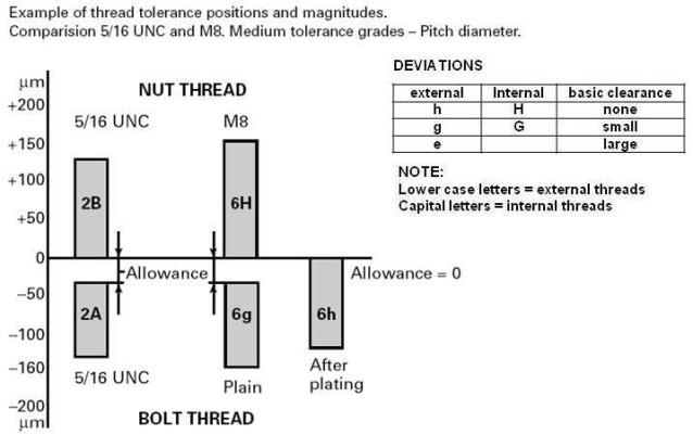
For better understanding of fits and tolerances, an example given on web site of Unbako (in Engineering Guide) is reproduced here.
Go to Top
Designation Method
A full designation for a metric thread includes information not only on the thread diameter and pitch but also a designation for the thread tolerance class. For example a thread designated as M12 x 1.25 – 5g6g indicates that the thread has a nominal diameter of 12 mm and a pitch of 1.25 mm (fine thread). The 5g indicates the tolerance class for the pitch diameter and 6g is the tolerance class for the major diameter.
A fit between threaded parts is indicated by the nut thread tolerance designation followed by the bolt thread tolerance designation separated by a slash. For example: M12 x 1 25- 6H/5g6g indicates a tolerance class of 6H for the nut (female) thread and a 5g tolerance class for the pitch diameter with a 6g tolerance class for the major diameter on bolt (male) thread.
Note:
Since for coated threads the tolerances apply to threads before coating (unless otherwise stated), the gap is taken up by the coating thickness. After coating, the actual thread profile must not cross the basic profile of the thread.
Unified inch screw threads are designated by the nominal size (screw number or basic major diameter), number of threads per inch, thread series symbol (UNC, UNF, etc.) and thread class symbol (e.g. 2A) in sequence as illustrated below.
¼ – 20 UNC – 2A or 0.250 – 20 UNC – 2A
10 – 32 UNF – 2A or 0.190 – 32 UNF – 2A
Where,
¼ and 10 are nominal size (fraction diameter or screw number, decimal equivalent is optional)
20 and 32 are number of threads per inch
UNC and UNF are thread form and series and
2A is thread class symbol.
Note:
At times number of threads per inch is not mentioned (as nominal diameter, thread form and series take care of it).
Go to Top
Manufacturing Operations for Threaded Fasteners
Heading, threading and heat treatment are the most important operations in threaded fastener manufacturing.
Heading
Heads can be made by forging or machining. When heads are forged, the flow lines of the material are continuous resulting in increased strength and a longer product life. It is recommended (ASME SF-568) that bolts and screws of property classes 4.8, 5.8, 8.8, 8.8.3, 9.8, 10.9, 10.9.3 and 12.9 in nominal thread diameters up to M20 inclusive with lengths up to 10 times the nominal product size or 150 mm, whichever is shorter, shall be cold headed.
Threading
Threads of a fastener can be made by grinding, cutting or rolling. Generally ground threads are not produced because of excessive machining costs. Cutting threads (e.g. turning) interrupt the grain flow of the material resulting in weaker threads. In rolling, threads are formed by plastically deforming a blank rather than cutting it (squeezing the blank between serrated dies). Threads formed by rolling will ensure that the grain flow follows the thread contour. Majority of standard fasteners have their threads formed by rolling. It is recommended that bolts and screws of property classes 4.8, 5.8, 8.8, 8.8.3, 9.8, 10.9, 10.9.3 and 12.9 in nominal thread diameters up to M20 inclusive with lengths up to 10 times the nominal product size or 150 mm, whichever is shorter, shall be roll threaded. Most threads are rolled before any heat treatment operation is carried out. Significant improvements in fatigue life can be achieved by rolling the thread after heat treatment. This improvement is due to compressive stresses being induced in the roots of the thread. However, because of the increased hardness of the bolt blank, the die life can be significantly reduced. Rolled threads provide a smooth finish, reducing the susceptibility to a fatigue failure that could propagate from a surface imperfection. Standards define acceptance criteria for thread laps that can initiate a fatigue crack. These standards appear to be the most commonly violated. Although often overlooked, they are critical to the fatigue life of the fastener.
Heat Treatment
Heat treatment is carried out to produce stronger fasteners. Hardening and tempering operations are carried out in heat treatment. For more information on heat treatment refer the article on testing and heat treatment.
Go to Top
Useful Information for Threaded Fasteners
Strain Hardening
Strain hardening is the increase in strength and hardness that results from plastic deformation below the recrystallization temperature (cold work). This effect is produced in austenitic stainless steel by reducing oversized bars to the desired final size by cold drawing or other process. The degree of strain hardening achieved in any alloy is limited by its strain hardening characteristics. In addition, the amount of strain hardening that can be produced is further limited by the variables of the process, such as the total amount of cross-section reduction, die angle and bar size. In large diameter bars, for example, plastic deformation will occur principally in the outer region of the bar, so that the increased strength and hardness due to strain hardening is achieved predominantly near the surface of the bar. That is, the smaller is the bar, the greater the penetration of strain hardening. Thus, the mechanical properties of a given strain hardened fastener are dependent not just on the alloy, but also on size of bar from which it is machined.
Surface Finishes
Generally all the products, unless otherwise ordered, are supplied in black thermal finish with a coat of rust preventive oil. It is also called Gun Barrel condition (as heat treated and oiled finish). Variety of coatings such as Dacromet, Corshield, Phospate, Zinc, Fluoro carbon or other as required are provided for corrosion resistance if ordered. While plating fasteners, take care of hydrogen embitterment problem. Research conducted on bolts with properties equivalent to Class 10.9 indicated that hydrogen-stress corrosion cracking may occur in hot-dip zinc-coated fasteners of Classes 10.9 and 12.9. It is recommended that they should not be hot-dip Zinc-coated. Adhesives and sealants are applied for thread sealing or prevent self-unlocking of fasteners in vibration related applications like a range of Loctite or other thread applicators. More in formation on surface finishes (e.g. zinc-coating) will be covered in an article on coating and plating in future.
Anti-seize Compounds
An anti-seize compound is used on the threads of fasteners in some applications. The purpose is to prevent galling of mating surfaces. Such compounds are frequently used with stainless steel fasteners to prevent this effect from occurring. In some applications it is used to allow the parts to be subsequently dis-assembled easily. They also provide a barrier to water penetration since the threads are sealed by use of the compound.
Tensile Stress Areas for Screw Threads
In calculating tensile stress area of a screw thread, diameter equal to mean of pitch diameter and minor diameter is used.
Length of a Bolt and Thread Stripping
Typically the first few pitches of a thread fastener can be only partially formed because of a chamfer etc. In view of this, it is a common practice to select bolt length such that at least one thread pitch protrudes out of the nut face. Nut thickness standards have been drawn up on the basis that the bolt will always fail due to tension before the nut thread strips. If the bolt breaks on tightening, it is obvious that a replacement is required. Thread stripping tends to be gradual in nature. If the thread stripping mode occurs, assemblies may enter into service which is partially failed. This may have disastrous consequences. Hence, the potential of thread stripping of both the internal and external threads must be avoided if a reliable design is to be achieved. Thus to avoid thread stripping, full height of the nut shall be used. To prevent thread stripping, when specifying nuts and bolts it must always be ensured that the appropriate grade of nut is matched to the bolt grade. In general, nuts of a higher property class (higher strength) can replace nuts of lower property class (because as explained above, the ‘weakest link’ is required to be the tensile fracture of the bolt).
Left / Right Thread Types
Unless otherwise stated, threads are normally Right Handed. This is the norm. This means that the nut screws on with a CLOCKWISE rotation. Left Hand threads are of course the opposite. Left Handed threads are used extensively in the Motor Industry and rotating equipment (e.g. pumps) to secure rotating parts such that the normal angular rotation would tend to tighten the nut. When working on rotating parts, always check the hand of the thread or refer the instruction manual.
Thread Identification
Following may be followed to identify threads for replacement / procurement of fasteners based on sample fastener.
For external threads, measure the diameter and see if the thread is (or may be) Imperial or Metric. Some times it is difficult – for example 5/16" & 8mm are very close together. Other method is to measure the number of threads in an inch. Lets say it comes to approximately 25.5. This equates to a 1mm pitch & if the diameter was 6mm this is almost certain to be an ISO Metric Coarse M6 thread. To find number of threads in an inch, roll the thread form onto a piece of paper and count treads in one inch length. Alternatively thread pitch gauges, existing threads of known size etc. may be used.
Determining the size of internal threads by direct measurement is very difficult. The best way is to try a selection of taps, plug type gauge or threads (screws / bolts of known thread) until one fits perfectly without any undue tightness.
Look at the history of the item. Old British machinery, tools etc. will have probably BSF/BSW threads. Items from USA will have UNF/UNC threads and items from Continental Europe will have ISO Metric threads.
SEMS
It is a screw or bolt which has a captive washer. The washer is frequently loose on the plain shank of the fastener, the shank diameter being equal to the effective diameter of the thread; the thread being rolled from this diameter. The major diameter of the screw being larger than the washer hole prevents it from coming off. The Illinois Tool Works (ITW) made machines that produced these patented pre-asSEMbled washers and screws. The s at the end of SEMs is thought to have been subsequently picked up because they are not usually purchased individually. In spite of the original patents and trademarks the word SEMS is generally recognized as a generic term applicable to screw and washer assemblies.
Fasteners Quality Act
In USA, the Fastener Quality Act (FQA), Public Law 101-592, was signed by President Bush on November 16, 1990. Since its enactment the FQA has been amended three times (Pub L. 104-113, Pub L. 105-234, and Pub L. 106-34) to further clarify and define the requirements of the original Act.
The Act protects the public safety by:
(1) requiring that certain fasteners sold in commerce conform to the specifications to which they are represented to be manufactured.
(2) providing for accreditation of laboratories engaged in fastener testing, and
(3) requiring inspection, testing and certification in accordance with standardized methods.
For more information on the act, please visit web site of NIST – http://ts.nist.gov/WeightsAndMeasures/fqa.cfm
Fasteners for Pressure Vessel according to PED / 97 / 23 / EC
The Pressure Equipment Directive (97/23/EC) was adopted by the European Parliament and the European Council in May 1997. Legislation across the European Union requires that all applicable items of pressure equipment placed on the market by May 2002 must be fully compliant with the PED 97 / 23 / EC. Fasteners have to be made from steel listed in EN 10269 or they have to be approved in a “Particular Material Appraisal”. Manufacturer has to give certificate according to EN 10204-3.1.B, stating that the products are approved in accordance with PED 97 / 23 / EC. For more information on the directive, please visit web site of Enterprise and Industry, European Commission – http://ec.europa.eu/enterprise/pressure_equipment/ped
As failure of fasteners may cause serious injury or death, for critical applications it is advisable to procure fasteners from reputed manufacturers only.
Unbrako and Sundaram Fasteners Limited are well known brands in India. Their website addresses are as under.
www.unbrako.in
www.sundram.com
