In rigging various types of hitches are used to hold loads. Safe working load limit of a sling depends on type of hitch, sling angle and D/d ratio. Information on types of hitches and effect of type of hitch, sling angle and D/d ratio on safe working load is given in this article.
Types of Hitches
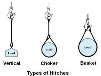
Every lift uses 1 of 3 Basic Hitches shown above – Vertical, Choker and Basket. Detail about various sling configurations using them is as under.
Single Vertical Hitch
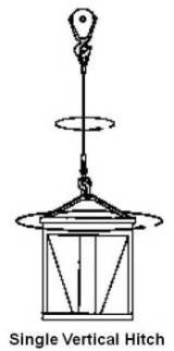
In single vertical hitch a sling is used to connect a lifting hook or other device to a load. In this configuration the total weight of the load is carried by a single leg, the sling horizontal angle is 90º (angle between horizontal line and sling), and the weight of the load can equal the maximum working load limit of the sling. This hitch provides absolutely no control over the load because it permits rotation. A tagline should be attached to prevent rotation which may damage the sling.
Bridle Hitch
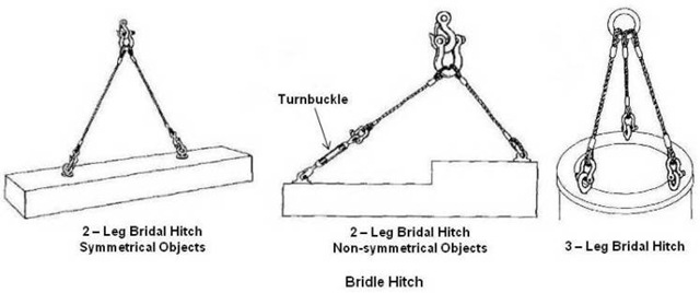
Two or more sling hitches can be used together to form a bridle hitch. This configuration provides good load stability when the load is distributed equally among the legs (symmetrical objects), the hook is directly over the load’s center of gravity and the load is raised level. In case of non-symmetrical objects (off-center loads), a sling leg may be fitted with a turnbuckle to adjust the length to level it. Instead of a turnbuckle, come-along of adequate capacity may be also used. Proper use of a bridle hitch requires that sling angles are carefully measured to ensure that individual legs are not overloaded. Because the load may not be distributed evenly, when more than two slings (3 or 4 leg slings) are used, load may be carried by only two legs while other legs are only balancing it. Unequal length sling legs may be one reason for this. In view of this, it is recommended to assume that the load is carried by two legs only and the sling may be rated as two leg sling. If a qualified rigger or rigging specialist ensures that the load is evenly distributed, the full use of all the legs is allowed.
Note:
All wire rope sling capacity tables (e.g. in ASTM B30.9 and Wire Rope Users Manual) consider all legs sharing equal loads.
Single Basket Hitch
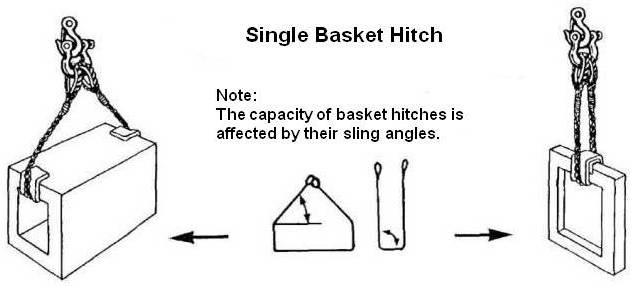
The single basket hitch is used to support a load by attaching one end of the sling to the hook, then passing the other end under the load and attaching it to the hook. One shall ensure that the load does not slide along the sling during lifting.
Double Basket Hitch
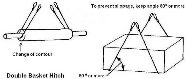
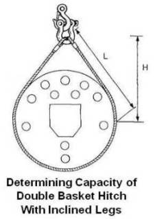
The double basket hitch consists of two basket hitches passed under the load. They must be placed under the load so that it is balanced. The lags of the hitches must be kept far enough apart to provide balance but not so far apart that low angles are created and the legs pull in towards the centre. The angle between the load and the sling should be approximately 60º or greater to avoid slippage. On smooth surfaces, both sides of the hitch should be snubbed against a change of contour to prevent the sling from slipping as load is applied. Otherwise use a double wrap basket hitch.
Double Wrap Basket Hitch
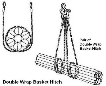
The double wrap basket hitch is a basket hitch wrapped completely around the load and compressing it rather than merely supporting it, as done by the ordinary basket hitch. The double wrap basket hitch can be used in pairs like the double basket hitch. This arrangement is used for handling loose material, pipes, rods, or a smooth cylindrical load because the sling is in full 360º contact with the load and tends to draw it together.
Single Choker Hitch
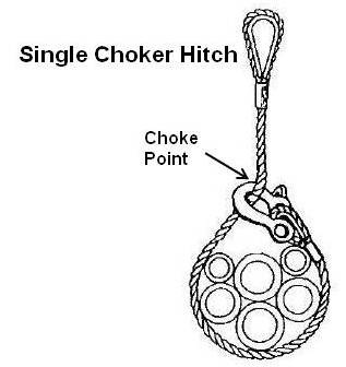
The single choker hitch forms a noose in the rope. It does not provide full 360º contact with the load. It should not be used to lift loads difficult to balance or loosely bundled. The hitch reduces lifting capacity of a sling as this method of rigging affects the ability of the wire rope components to adjust during the lift, places angular loading on the body of the sling and creates a small diameter bend in the sling at the choke point.
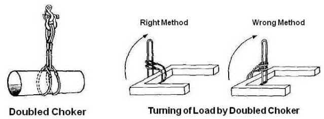
Doubled Choker
The single choker hitch can be doubled up to provide twice the capacity or to turn a load as shown below (Doubling a single choker hitch is not the same as using a double choker hitch.).
Double Choker Hitch
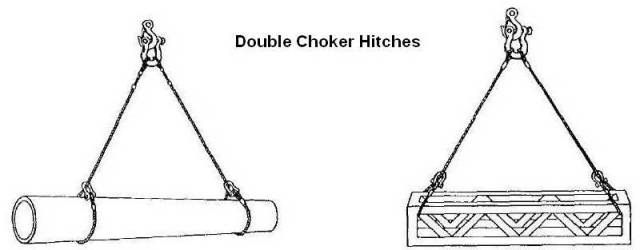
The double choker hitch consists of two sling chokers attached to the load and spread to provide load stability.
Double Wrap Choker Hitch
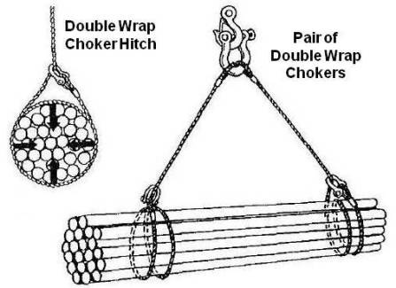
Double wrap choker hitch is formed by wrapping the sling completely around the load and hooking it into the vertical part of the sling. This hitch is in full 360º contact with the load and tends to draw it tightly together. It can be used either single on short, easily balanced loads or in pairs on longer loads.
Endless Slings or Grommet Slings
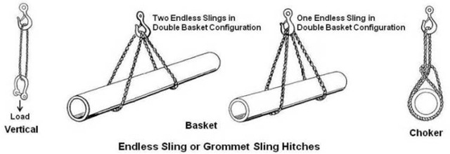
Endless slings are used for all three types of basic hitches as shown above. They are made from wire ropes, chains and synthetic materials. They are flexible but tend to wear faster than other slings because normally they are not fitted with fittings and deforms when bent over hooks.
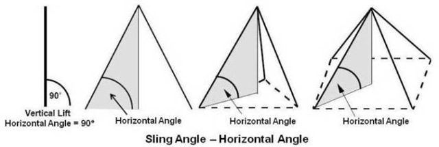
Sling Angle
The loading in any type of sling is affected by the angle of the sling leg. Any angle other than vertical (sling angle = 90º) at which the sling is rigged, increases the loading (tension) on the sling. Due to this, sling’s working load limit reduces. As the angle decreases the stress imposed on the leg of a sling increases. This angle, which is measured between a horizontal line and the sling leg or body, is called sling angle or horizontal angle as shown below.
Sling’s working load limit (WLL) can be calculated by applying trigonometrical function (for stress calculation) as under.
Sling’s working load limit = Sling’s vertical capacity x sine of horizontal angle.
For easy of understanding and 'day-to-day' practical calculation above equation can be written as under.
Sling’s Working Capacity = Factor x Sling’s Rated Capacity
Where Factor shall be taken based on sling angle from following table.
| Sling Angle in Degrees | Factor | Sling Angle in Degrees | Factor |
|---|---|---|---|
| 15 | 0.259 | 55 | 0.819 |
| 20 | 0.342 | 60 | 0.866 |
| 25 | 0.423 | 65 | 0.906 |
| 30 | 0.500 | 70 | 0.940 |
| 35 | 0.574 | 75 | 0.966 |
| 40 | 0.643 | 80 | 0.985 |
| 45 | 0.707 | 85 | 0.996 |
| 50 | 0.766 | 90 | 1.000 |
As sling stresses increase tremendously with angles smaller than 45°, it is recommended not to use sling angle less than 30º. Low sling angles also create large horizontal compressive forces in the load which may be sufficient to cause buckling, especially in long flexible loads. If two or more slings are used, the minimum horizontal angle shall be used for calculating working capacity.
As measuring of sling angle can be difficult on a construction site, use the following methods to estimate safe working loads for common sling configurations.
Each rule is based on the safe working load of a sling in vertical hitch of a given size and material and the ratio H/L, where H is the vertical distance of the hook to the top of the load and L is the distance, measured along the sling, from the saddle of the hook to the top of the load as shown below.
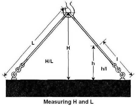
If it is not possible to measure the entire length of the sling, measure along the sling from the top of the load to a convenient point and call it distance “l”. From this point measure vertically down to the load and call it distance “h”. The ratio h/l will be the same as the ratio H/L as shown in above sketch. Either H/L or h/l will apply equally to the following methods.
Note:
When sling legs are not of equal length, use smallest H/L ratio.
Capacity of Bridle Hitches (2-Leg)
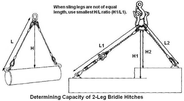
WLL = WLL (of Single Vertical Hitch) x (H/L) x 2
Capacity of Bridle Hitches (more than 2 legs)
Three and four leg bridle hitches are rated equally to account for the possibility of unequal load distribution in a four leg hitch.
WLL = WLL (of Single Vertical Hitch) x (H/L) x 3
The three leg hitches are less susceptible to unequal distribution since the load can tilt and equalize the loads in each leg. However, lifting an irregularly shaped, rigid load with a three leg hitch may develop unequal loads in the sling legs. To be safe, use the formula for a two leg bridle hitch under such circumstances.
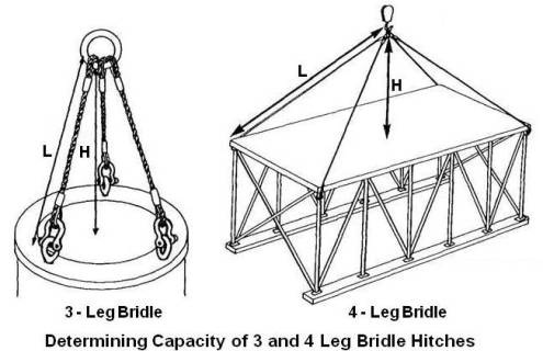
Note:
The rated capacity of a multi-leg sling is based on the assumption that all legs are used. If this is not the case, de-rate the sling assembly accordingly and hook all unused legs to the crane hook so they will not become snagged during the lift.
Capacity of Single Basket Hitch
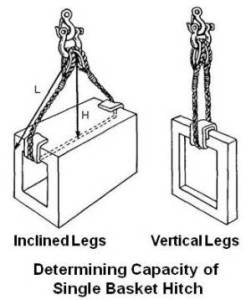
For single basket hitch, sling capacity is as under based on sling configuration.
For inclined legs, WLL = WLL (of Single Vertical Hitch) x (H/L) x 2
For vertical legs, WLL = WLL (of Single Vertical Hitch) x 2
Capacity of Double Basket Hitch
For double basket hitch, sling capacity is as under based on sling configuration.
For inclined legs, WLL = WLL (of Single Vertical Hitch) x (H/L) x 4
For vertical legs, WLL = WLL (of Single Vertical Hitch) x 4
Capacity of Double Wrap Basket Hitch
Depending on configuration, safe working loads are the same as for the single basket hitch or the double basket hitch.
Capacity of Single Choker Hitch
When the load is hanging free, and the choke was not forced down towards the load, the normal sling angle is about 45 degree.
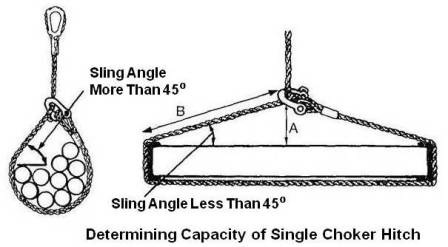
Based on sling angle (formed by the choker), capacity of single choker hitch is as under.
For sling angle of 45º or more, WLL = WLL (of Single Vertical Hitch) x ¾
Sling angles of less than 45º are not recommended. If they must be used,
WLL = WLL (of Single Vertical Hitch) x (A/B)
In a choker hitch, sling shall be long enough so that the choker fitting chokes on the wire rope body and never on the fitting (sleeve/ferrule).
Capacity of Double Choker Hitch
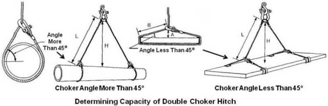
Based on sling angle (formed by the choker), capacity of double choker hitch is as under.
For sling angle of 45º or more, WLL = WLL (of Single Vertical Hitch) x ¾ x (H/L) x 2
Sling angles of less than 45º are not recommended. If they must be used,
WLL = WLL (of Single Vertical Hitch) x (A/B) x (H/L) x2
Capacity of Double Wrap Choker Hitch
Depending on configuration, WLLs are the same for the single choker hitch or the double choker hitch.
Capacity of Endless/Grommet Slings
Although grommet slings support a load with two legs, their WLL is usually taken as 1.5 times the WLL of a single vertical hitch. This reduction allows for capacity lost because of sharp bends at the hook or shackle.
Center of Gravity
Center of gravity is the point around which an object’s weight is evenly balanced. The entire weight may be concentrated at this point.
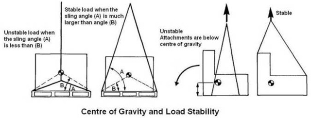
It is always important to rig the load so that it is stable. For this the load’s centre of gravity must be directly under the main hook and below the lowest sling attachment point before the load is lifted.
A suspended object will always move until its centre of gravity is directly below its suspension point. To make a level or stable lift, the crane hook block must be directly above this point before the load is lifted as shown below.
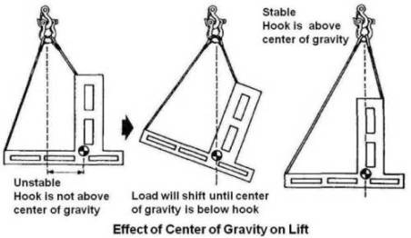
For load stability it is equally important to ensure that the support points of a load (i.e. where the slings are attached to the load) lie above its centre of gravity. Under suspension, an object’s centre of gravity will always seek the lowest level below the point of support. This knowledge is especially important for lifting pallets, skids, or the bas of any object since they all have a tendency to topple. This type of load will be stable if the attachments are above the centre of gravity as shown below.
An object symmetrical in shape and uniform in composition will have its centre of gravity at its geometric centre. With odd shaped objects, the centre of gravity can be difficult to locate. In such cases the rigger must guess where it lies, rig accordingly and signal for a trial lift. The centre of gravity will lie somewhere along a line drawn vertically from the hook down through the load. The rigger than adjust the slings accordingly to balance the load. If any load tilts more than 5º after it is lifted clear of the ground it should be landed and rigged over again.
It may be noted that when the centre of gravity is closer to one attachment point than the other, the sling legs must be unequal in length. In this case their angles and loads will also be unequal.
Loading at Pick Points for Off-Centre Centre of Gravity Objects
When the center of gravity is not equally spaced between the pick points, the sling and fittings will not carry an equal share of the load. The sling connected to the pick point closest to the center of gravity will carry the greatest share of the load. The load carried by each pick point can be calculated as shown below.
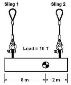
For above case, load carried by slings 1 and Sling 2 will be,
Sling 1 = (10 T x 2 m) / (8 m + 2 m) = 2 T
Sling 2 = (10 T x 8 m) / (8 m + 2 m) = 8 T
The above calculation is based on the fact that for balancing, torque (load x length of lever arm) generated by both the pick points shall be equal and opposite.
D/d Ratio
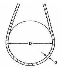
The capacity of a wire rope sling can be greatly affected by being bent sharply around pins, hooks, or parts of a load. The wire rope industry uses the term “D/d ratio” to express the severity of bend. “D” is diameter of curvature that the rope or sling is subjected to and “d” is the diameter of the rope. The minimum D/d ratio is usually taken as 20 which correspond to 92 % efficiency. As wire ropes are usually at lease 8 % stronger than the catalogue strength, the bent sling at D/d = 20 is therefore considered 100 % efficient. In case wire rope slings are used for smaller D/d ratio, sling capacity shall be decreased based on wire rope efficiency as per following graph. This curve is based on static loads and applies to 6-strand class 6×19 and 6×37 wire ropes.
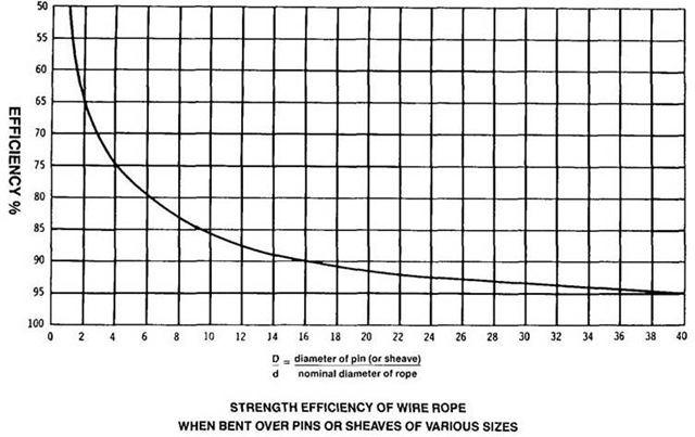
Based on above graph, if the shackle or object has 2 times the diameter of a wire rope sling (D/d = 2) the basket sling capacity must be reduced by 35 % as shown below.
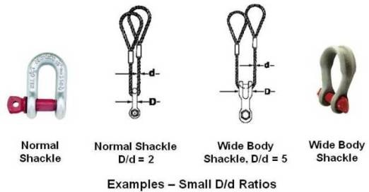
To increase d/d ratio and sling capacity, use wide body shackle. If D/d ratio is 5 after using wide body shackle, sling capacity shall be reduced by about 20 %.
Load hooks must have sufficient thickness to ensure proper sling D/d ratio, particularly when using slings in an inverted basket hitch; that is the sling body is placed into the hook and the sling eyes are facing downward.
Preventing Sling Damage
Make sure loads are not bolted to the floor. In winter, make sure that the load is not frozen to the ground.
If slings are used above spreader, select their size based on weight of load to be lifted plus weight of spreader.
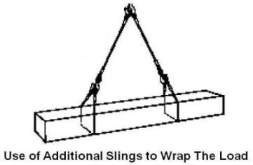
Use additional single leg slings to wrap around the load as shown below. If they get damaged they are less costly to replace.
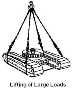
For large loads a 4-leg bridle sling can be made into a double basket sling by adding 2 single leg slings. These single leg slings can be made of larger diameter rope to better withstand load conditions as shown below. They are less expensive to replace than the entire 4-leg sling if they get damaged.
Use proper corner protection. A sharp steel edge may cut through wire rope sling; at least it will permanently damage the sling. As shown below, sliced steel pipes have proven to an effective corner protector. For square and round objects proper wooden padding will be sufficient. Before making the final lift, do a trial lift. Check that the padding is strong enough and does not crack under the load weight.
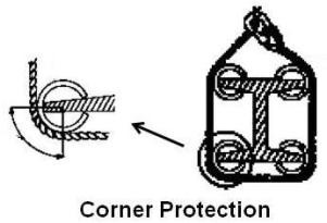
Do not place the splice sleeves, rope thimbles, or sling hooks around corners as shown below. A sleeve failure will result in the failure of the sling.

Acknowledgement:
In this article, figures and technical information from Construction Safety – Slings published by Construction Safety Association of Ontario are used.
