All mater is considered to be made up of unit substances known as chemical elements. These elements are made up of atoms. When atoms are brought together, they tend to arrange themselves in infinitesimal cubes, prisms, and other symmetrical shapes. These geometrical units, joined to each other like perfectly fitted blocks make the larger structure known as crystals. Information about structure of an atom and a crystal is given in this article.
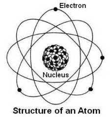
Structure of an Atom
While each chemical element is made up of atoms, it is the difference in atomic structure that gives the element its characteristic properties. An atom consists of a minute positively charged central part known as nucleus. The nucleus is made up of protons and neutrons and is surrounded by electrons. Electrons are spinning on their axis and simultaneously around the nucleus at very high velocity.
Protons are particles of positive electricity, electrons are particles of negative electricity and neutrons are particles without any electricity. The mass of proton, neutron and electron is approximately 1.673 x 10⁻²⁴ g, 1.675 x 10⁻²⁴ g and 9.11 x 10⁻²⁸ g respectively. Thus mass of a proton is almost equal to that of a neutron and mass of an electron is approximately 1/1800 the mass of a proton. Due to this, almost the entire mass of the atom is concentrated in the nucleus. The diameter of the nucleus is of the order of 10-12 cm and is very small compared with the diameter of an atom which is approximately 10-8 cm (one angstroms). Since the electron and proton have equal but opposite electrical charge, the neutral atom must contain an equal number of electrons and protons. Atomic number of an element is the number of either electrons or protons in its atom. Atomic number of iron is 26 since there are 26 electrons balancing 26 protons in iron atom. The weight of an atom is approximately equal to the total weight of protons and neutrons and is called atomic weight of the element.
It is not possible to determine exact orbit of an electron but its position is determined by the probability that it will be found in a given region (state) of the atom. This probability is represented mathematically by a certain wave function. The solution of the wave equation leads to four quantities known as the quantum numbers n, l, ml and ms. Of these, n is the principal quantum number related with the total energy of the electron in a particular state. The state is known as a shell. The letters K, L, M, N, etc. have been introduced to signify n = 1, 2, 3, 4, and so on. Each shell is further subdivided into energy states or levels known as subshells. Subshells are determined by the other three quantum numbers l, ml and ms which are measure of the angular momentum, the component of angular momentum in a specified direction and the spin of the electron on its own axis respectively.
The number of electrons in each shell varies with the shell position. The maximum number of electrons in a given shell is 2n2, where n is the principal quantum number of the shell. Thus electrons distribution in various shells will be as under.
The first or the lowest-energy quantum shell K, (n=1) contains 2n2 i.e., 2(1)2 = 2 electrons.
The second quantum shell L, (n=2) contains 2(2)2 = 8 electrons.
The third quantum shell M, (n=3) contains 2(3)2 = 18 electrons.
The fourth quantum shell N, (n=4) contains 2(4)2 = 32 electrons, and so on.
The number of subshells in a shell depends on the shell. In nth shell there are n subshells (energy levels). Thus in K shell (n=1) there is only one subshell (n=1), in L shell (n=2) there are two subshells (n=2) and so on.
The number of electrons in each subshell depends on the second quantum number l. The number of electrons in a subshell can be only 2(2l+1). The second quantum number l may have values from 0 to (n – 1). For example, if l = 0, 1 or 2 the number of electrons are 2, 6 or 10 respectively.
Based on above, for each shell, number of subshells (energy levels) and number of electrons in each subshell can be tabulated as under.
| Shell number, n = | 1 | 2 | 3 | 4 | 5, 6, 7 |
| Shell Name | K | L | M | N | O, P, Q |
| No. of subshells = value of n | 1 | 2 | 3 | 4 | So on |
| No. of electrons in subshells, 2(2l+1), for l = 0 to l = (n-1). | 2 | 2,6 | 2,6,10 | 2,6,10,14 | So on |
| Energy levels corresponding to l | s | s,p | s,p,d | s,p,d,f | So on |
| Total number of electrons | 2 | 8 | 18 | 32 | So on |
The letters s, p, d, f, g and h have been introduced to signify l = 0, 1, 2, 3, 4, 5, so that the energy level corresponding to n = 1 and l = 0 is called the 1s level, that corresponding to n = 2 and l = 0 is called 2s, that corresponding to n = 2 and l = 1 is called 2p level, etc. The figure given below schematically shows some of the possible electron states in an atom and their energy levels.
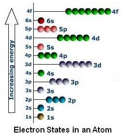
Each dot (sphere) may be occupied by two electrons of opposite spin. It may be noted that the energy levels are overlapping each other at larger values of n.
Based on above, distribution of electrons in different shells for iron (26 electrons) will be as shown below.
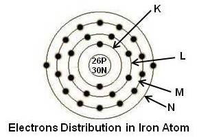
It may be noted that iron atom has first and second shell full, third shell partly filled with 14 electrons and fourth shell also partly filled with 2 electrons. Third and fourth shells are partially full to satisfy position of a subshell based on their energy level.
Classification of Elements
The chemical elements may be roughly classified into three groups, metals, metalloids and nonmetals.
Elements considered to be metals have several characteristic properties as under.
- In the solid state they exist in the form of crystals.
- They have relatively high thermal and electrical conductivity.
- They have the ability to deform plastically.
- They have relatively high reflectivity of light (metallic luster).
The metals are on the left side of periodic table and constitute about three-fourths of elements.
Metalloids resemble metals in some respects and nonmetals in others. Generally they have some conductivity but little or no plasticity. Examples of metalloids are carbon, boron and silicon.
The remaining elements are known as nonmetals. This includes the inert gases, the elements in Group VIIA, and N, O, P and S.
The States of Matter
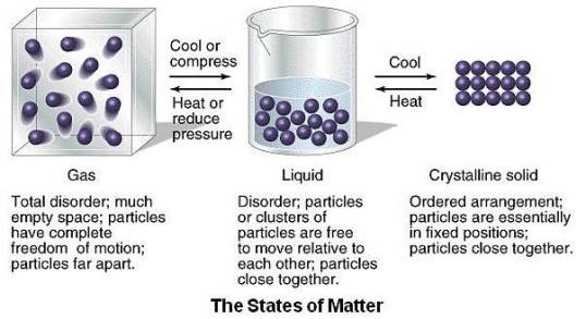
The states of matter represent ‘classes’ of the type of molecular motion found at different temperatures. As shown in the figure given below, there are three states of matter – solid, liquid and gas.
Solid
When the temperature is low, the atoms/molecules stick together, and the result is a state of matter that is rigid and dense.
At low temperatures the nuclei of the atoms of a solid vibrate about an equilibrium position but are trapped in their lattice positions, unable to flow or diffuse. The intermolecular forces are stronger than the average thermal energy of the system. Atoms of crystalline solid occupy orderly position (crystal structure). Even amorphous solids have relatively good spatial ordering, especially over small distances (10-100 molecules).
Liquid
As the binding energy to the lattice site is overcome by thermal energy, the atoms/molecules in the solid may slip past each other but maintain close contact. The overall substance is fluid, but not very compressible. Some ordering persists among atoms/molecules, but usually only over the size of a few molecular diameters.
Gas
Gases consist of large numbers of molecules (or atoms, in the case of the noble gases) that are in continuous random motion. Attractive forces between gas molecules are negligible. They are described by the kinetic theory of gases.
Atom Binding
It is the characteristic of the solid state that all true solids exhibit a crystal structure which is a definite geometric arrangement of atoms or molecules. Some materials, such as glass or tar, that are rigid at room temperature do not have a regular arrangement of molecules but rather the random distribution that is typical of the liquid state. These materials are not true solids but rather supercooled liquids.
Atoms or molecules are held together due to bonding between them. The four possible types of bonds are as under.
Ionic Bond
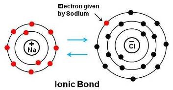
Atoms are at their most stable condition when they have no partially-filled electron shells. In ionic bonding a metal gives an electron to an atom which needs extra electrons. This causes both atoms to be charged. One has a positive charge (it has more protons than electrons) and the other a negative charge. This causes an attraction between the atoms. Sodium chloride, ordinary table salt is an example of ionic bond. As shown above, when sodium and chlorine atoms are placed together, there is a transfer of electrons from the sodium to chlorine atoms, resulting in a strong electrostatic attraction between the positive sodium ions and negative chlorine ions.
Ionic bonding occurs between metal atoms and nonmetal atoms. Metals usually have 1, 2, or 3 electrons in their outermost shell. Nonmetals have 5, 6, or 7 electrons in their outer shell. To become stable, the metal atom wants to get rid of one or more electrons in its outer shell and nonmetal atom wants to gain electrons.
Materials bonded this way are usually brittle with poor electrical conductivity.
Covalent Bond
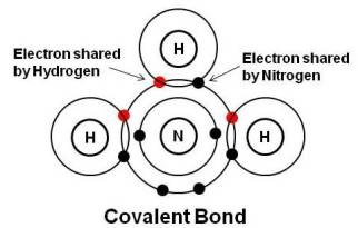
Some atoms like to share electrons to complete their outer shells. Each pair of shared atoms is called a covalent bond. Covalent bonds are called directional because the atoms tend to remain in fixed positions with respect to each other. As shown above, nitrogen has 5 electrons in the outer shell and needs 3 electrons to complete shell. Hydrogen has 1 electron in the outer shell. To attain a stable structure, a nitrogen atom shares the electrons of three hydrogen atoms and in turn shares three of its electrons with the three hydrogen atoms to form ammonia (NH3). The bond between two nonmetal atoms is usually a covalent bond.
Covalent bonds are also very strong. Examples include diamond, and the O-O and N-N bonds in oxygen and nitrogen gases.
Metallic Bond
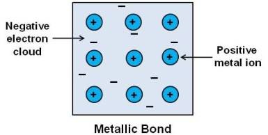
A common characteristic of metallic elements is that they contain only one to three electrons in the outer shell. When an element has only one, two or three valence electrons (i.e. electrons in the outer shell), the bond between these electrons and the nucleus is relatively weak. Due to this, when atoms of a metal are grouped together, the outer electrons leave individual atoms to become part of common “electron cloud.â€
In a metallic bond, each atom gives up its outer electrons to the formation of the negative “electron cloud” and becomes slightly positively charged. These positively charged metallic ions are held together by virtue of their mutual attraction for the negative electron cloud. Since the electrons are free to move, they lead to good thermal and electrical conductivity. This is schematically illustrated in the figure given above. The metallic bond may be thought of as an extension of the covalent bond to a large number of atoms.
Van der Waals Forces
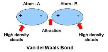
This type of bond arises in neutral atoms such as inert gases. When the atoms are brought close together there is a separation of the centers of positive and negative charges, and a weak attractive force results. It is of importance only at low temperatures when the weak attractive force can overcome the thermal agitation of the atoms.
Structure of a Crystal
A solid is one of the three states of a matter in which atoms are closely packed as compared to the other states, gas and liquid. When the atoms or molecules in a solid are arranged in an irregular fashion, it is known as amorphous solid. On the other hand, when atoms or molecules are arranged in some regular fashion, it is known as crystalline solid. When a solid has a crystalline structure, the atoms are arranged in repeating structures called unit cells, which are the smallest units that show the full symmetry of a crystal. If we take unit cells and stack them, we produce a lattice. The three dimensional network of imaginary lines connecting the atoms of a crystal is called the space lattice. Space lattices created by stacking cubic and hexagonal unit cells are shown below.
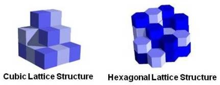
Notice that once we begin stacking the unit cells, we never change the orientation of any subsequent unit cells as they stack. In other words, once the orientation of a unit cell is determined, all unit cells within that lattice have the same orientation. The different colors are just to show the separate cells – each unit cell is identical.
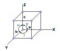
As shown in above figure, the specific unit cell for each material is defined by its parameters, which are the edges of the unit cell a, b, c and the angles α (between b and c), β (between a and c) and γ (between a an b).
There are only 14 possible types of space lattices, known as Bravais Lattices and fall into seven crystal systems as under.
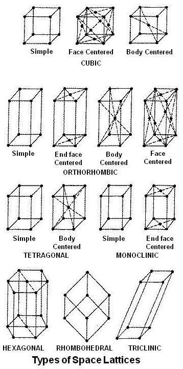
The crystal systems are,
| Sr. No. | Category | Edge Lengths | Internal Angles |
|---|---|---|---|
| 1 | Cubic | a = b = c | α = β = γ = 90° |
| 2 | Orthorhombic | a ≠b ≠c | α = β = γ = 90° |
| 3 | Tetragonal | a = b ≠c | α = β = γ = 90° |
| 4 | Monoclinic | a ≠b ≠c | α = γ = 90° ≠β |
| 5 | Hexagonal (Three equal coplanar axes at 120° and a fourth unequal axis perpendicular to their planes) | a = b ≠c | α = β = 90°, γ = 120° |
| 6 | Rhombohedral (trigonal) | a = b = c | α = β = γ ≠90° |
| 7 | Triclinic | a ≠b ≠c | α ≠β ≠γ ≠90° |
Fortunately, most of the important metals crystallize in either the cubic or hexagonal system and only three types of space lattices are commonly encountered: the b.c.c (body centered cubic), the f.c.c. (face centered cubic) and the c.p.h. (close packed hexagonal).
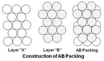
To form the strongest metallic bonds, metals are packed together as closely as possible. Several packing arrangements are possible. To understand them, instead of atoms, imagine marbles that need to be packed in a box. The marbles would be placed on the bottom of the box in neat orderly rows and then a second layer begun. The second layer of marbles cannot be placed directly on top of the other marbles and so the rows of marbles in this layer move into the spaces between marbles in the first layer. The first layer of marbles can be designated as A and the second layer as B giving the two layers a designation of AB as shown in the figure given below.
Packing marbles in the third layer requires a decision. Again rows of marbles will nest in the hollows between atoms in the second layer but two possibilities exist. If the rows of marbles are packed so they are directly over the first layer (A) then the arrangement could be described as ABA. Such a packing arrangement with alternating layers would be designated as ABABAB. This ABAB arrangement is called close packed hexagonal (CPH) as shown in the figure given below.
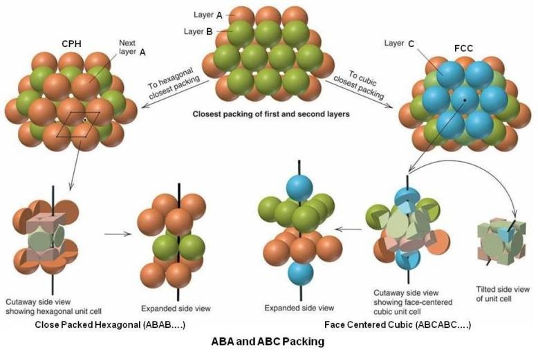
If the rows of atoms are packed in this third layer so that they do not lie over atoms in either the A or B layer, then the third layer is called C. This packing sequence would be designated ABCABC, and is also known as face-centered cubic (FCC) as shown in the figure given above. Both arrangements give the closest possible packing of spheres leaving only about a fourth of the available space empty.
A third common packing arrangement in metals, the body-centered cubic (BCC) unit cell has atoms at each of the eight corners of a cube plus one atom in the center of the cube. It may be noted that BCC arrangement is not as closely packed as CPH and FCC.
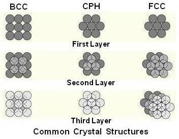
For comparison, all the three types of packing arrangements are shown together in the figure given below.
During crystallization, if atoms are not packed as per required sequence of packing arrangement (say ABAB, ABCABC, etc.), it is called stacking fault.
The arrangement of atoms in unit cell of above three types is explained below. For explaining their construction in the figures given below, atom is represented as a point (center image) and more accurately as a sphere as they are actually in their lattice structure (left and right images). The volume of atoms in a cell per the total volume of a cell is called the packing factor.
Body Centered Cubic Lattice
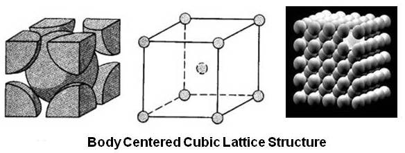
A body centered cubic cell has one atom in the centre of the cube and one atom each at all corners. Because each of the corner atoms is the corner of another cube, the corner atoms in each unit cell will be shared among eight unit cells. Thus the BCC unit cell consists of a net total of two atoms, the one in the center and eight eighths (equal to one) from the corners. Atomic packing factor for this type of lattice is 0.68. Examples of metals that crystallize in this type of structure are alpha (α) iron, chromium, molybdenum, tungsten, vanadium, etc.
Face Centered Cubic Lattice
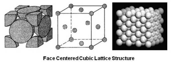
A face centered cubic cell has an atom at each corner of the cube and in addition, one atom at the intersection of the diagonals of each of the six faces of the cube. As the atom in the face is shared with the adjacent cell, FCC unit cells consist of a net total of four atoms, eight eighths (one) at the corners and six halves (three) in the faces. Atomic packing factor for this type of lattice is 0.74. This also shows that FCC structure is more densely packed than the BCC structure. Examples of metals that crystallize in this type of structure are gamma (γ) iron, aluminum, nickel, copper, gold, silver, etc.
Close Packed Hexagonal
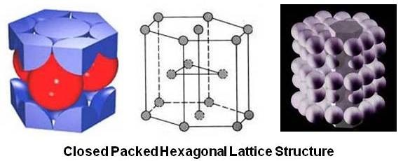
The usual picture of the close packed hexagonal lattice shows two basal planes in the form of regular hexagons with an atom at each corner of the hexagon and one atom at the center. In addition there are three atoms in the form of a triangle midway between the two basal planes. If the basal plane is divided into six equilateral triangles, the additional three atoms are nestled in the center of alternate equilateral triangle. It can be calculated that this type of unit cell consist of a net total of six atoms. Atomic packing factor for this type of lattice is 0.74, same as that of FCC lattice. Examples of metals that crystallize in this type of structure are magnesium, zinc, cadmium, etc.
Unit cell structures determine some of the properties of metals. For example, FCC structures are more likely to be ductile than BCC or CPH.
Polymorphism and Allotropy
Polymorphism is the property of a material to exist in more than one type of space lattice in the solid state. If the change in structure is reversible, then the polymorphic change is known as allotropy. Iron has allotropy property. When iron crystallizes at 2800°F it is b.c.c. (δFe), at 2554°F the structure changes to f.c.c. (γFe), and at 1670°F it again becomes b.c.c. (αFe).
Crystallographic Planes and Directions
Miller indices is a system of notation that denotes the orientation of the faces of a crystal and the planes and directions of atoms within that crystal. It gives information in terms of crystallographic planes and directions with respect to three principal axes.
Miller indices h,k,l and u,v,w are used to express lattice planes and directions. The layers of atoms or the planes along which atoms are arranged are known as atomic or crystallographic planes. These planes are designated as (hkl). [uvw] is used to show direction in the lattice.
Miller Indices of a Plane
A crystallographic plane is specified in terms of the length of its intercepts on the three axes.
To designate Miller indices of a plane, one corner of a unit cell is assumed to be the origin of the space coordinates, and any set of planes is identified by the reciprocals of its intersection with these coordinates. The unit of the coordinates is the lattice parameter of the crystal. If a plane is parallel to an axis, it intersects it at infinity (∞) and 1/∞ = 0. A generic Miller index is denoted by (hkl). If a plane cuts any axis on the negative side of the origin, the index will be negative and is indicated by placing a bar (minus) sign above the index. For example, if k is negative, it will be shown as ¯k. Miller indices of a plane passing through origin of space coordinates can not be determined without changing the location of the origin.
Note:
As per convention, bar sign, ¯ shall be placed above k as shown above 1 in the figure given below to show plane ABGF. As it is not possible to show it above k due to limitation of PC, it is shown ahead of it.
The above rules to find Miller indices may simply be followed in the sequence given below.
Determine the intercepts of the face along the crystallographic axes, in terms of unit cell dimensions.
- Take the reciprocals.
- Obtain Miller indices by clearing fractions and reducing them to lowest integer having the same ratio.
- The following three examples will help in understanding the sequence.
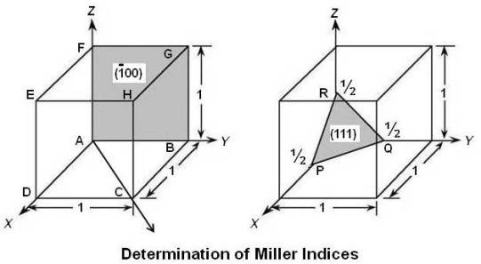
Above figure shows a cubic lattice. The unit cell’s dimensions are a = b = c = 1. Miller indices of different planes are calculated as under.
Example 1: Miller indices of plane PQR (the plane is shown in above figure on RHS)
Intercepts with X, Y and Z axis: ¹â„â‚‚, ¹â„â‚‚, ¹â„â‚‚
Reciprocals: 1/¹â„â‚‚, 1/¹â„â‚‚, 1/¹â„â‚‚, = 2, 2, 2
Reciprocals (after reducing to lowest integer): 1, 1, 1
This plane has Miller indices of (111)
Example 2: Miller indices of plane ABGF (the plane is shown in above figure on LHS)
Since the plane ABGF is passing through the origin, change the location of the origin. For convenience, take the point D as new origin. The plane ABGF now cuts the X axis at (-) 1 but is parallel to Y axis (DC) and Z axis (DE). Now determine Miller indices as under.
Intercepts with X, Y and Z axis: -1, ∞, ∞
Reciprocals: 1/-1, 1/∞, 1/∞ = -1, 0, 0
Reciprocals (already clear of fraction and with lowest integer): -1, 0, 0
This plane has Miller indices of (¯100).
Note that the bar (¯) sign in front of 1 shows that the plane ABGF cuts the X axis in negative direction.
Example 3: Miller indices of a plane having X, Y, and Z intercepts to be 2, 1, and 3 respectively (for this example, figure is not given)
Intercepts with X, Y and Z axis: 2, 1, 3
Reciprocals: 1/2, 1/1, 1/3
Clear fractions (multiply by 6): 3, 6, 2
Reciprocals (already with lowest integer): 3, 6, 2
This plane has Miller indices of (362)
Braces signify a family of planes of the same “form†(which are equivalent in the crystal). Thus while (hkl) is used for a crystallographic plane, {hkl} is used to show family of crystallographic plans (hkl), (lhk), (hlk), etc.
Family of cube faces of a cubic crystal can be shown as: {100} = (100) + (010) + (001) + (¯100) + (0¯10) + (00¯1).
In the same way while [uvw] is used for a crystallographic direction, <uvw> is used to show a family of equivalent sets of directions, such as [100], [¯100], [010], [0¯10], [001] and [00¯1] is designated as <100>.
In the cubic system, planes having the same indices regardless of order or sign are equivalent.
Indices of a Direction
Crystallographic directions are indicated by integers in brankets: [uvw].
Reciprocals are not used to determine the indices of a direction. In order to arrive at a point on a given direction, consider that starting origin, it is necessary to move a distance u times the unit distance a along the X axis, v times the unit distance b along the Y axis, and w times the unit distance c along the Z axis. If u, v and w are the smallest integers to accomplish the desired motion, they are the indices of the direction and are enclosed in square brackets [uvw]. For example, in above figure, to determine the direction AC, starting at the origin (point A), it is necessary to move one unit along the X axis to point D and one unit in the direction of Y axis to reach point C. The direction AC would have indices of [110]. It may be noted that value of w is taken as zero since it is not required to move any distance on Z axis to reach point C.
In crystallography, a direction is always perpendicular to the plane having the same indices. It can be seen in the figure given below that the direction FD, [110] is perpendicular to the plane BCGH, (110).
![(110) and [110] in a Simple Cubic Structure](http://practicalmaintenance.net/wp-content/uploads/110-and-110-in-a-Simple-Cubic-Structure.jpg)
Miller – Bravais system
Miller Bravais indices are used to specify planes and directions in the close packed hexagonal (cph) structure, giving four indices (hkil).
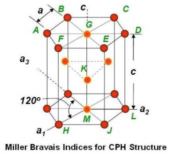
As shown in the figure given above, these indices are based on four axes. Three axes a1, a2 and a3 are 120° apart in the basal plane and the vertical c axis which is normal to the basal plane. The third index (i) is related to the first two (h and k) by the relation: i = – (h + k). Ideal c/a is approximately 1.633.
Packing of Atoms on a Plane
An approximate idea of the packing of atoms on a particular plane may be obtained by visualizing a single unit cell of the b.c.c. and f.c.c. structure. Considering the atoms at the lattice points, the number of atoms on a particular plane would be as under.
| Plane | b.c.c. | f.c.c. |
|---|---|---|
| (100) | 4 | 5 |
| (110) | 5 | 6 |
| (111) | 3 | 6 |
| (120) | 2 | 3 |
| (221) | 1 | 1 |
In a crystal structure, there are two types of atomic densities as under.
Linear Density
Number of atoms per length whose centers lie on the direction vector for a specific crystallographic direction.

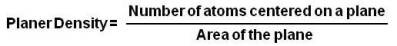
Planer Density
Number of atoms per unit area that are centered on a particular crystallographic plane.
Properties of a material in general depend on linear and planer density.
For example, speed of sound depends on directions and slip (deformation in metals) depends on linear and planar density. Slip occurs on planes that have the greatest density of atoms in direction with highest density. We can say along closest packed directions on the closest packed planes (for detail, please refer article on plastic deformation and fracture).
Single Crystals Vs Polycrystals
Some engineering applications require single crystals. For example, sometimes turbine blades are made from single crystal to improve high temperature mechanical properties.
However, most engineering materials consisting of many crystals and are known as polycrystalline materials. In these materials, each “grain” is a single crystal. Typically, size of a crystal range from 1 nm to 2 cm (i.e., from a few to millions of atomic layers).
A material is called isotropic if it has identical properties in all directions. If properties are different in different directions, it is called anisotropic material.
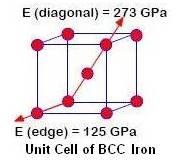
In single crystals, properties often vary with direction and hence they are anisotropic. For example, as shown in the above figure the modulus of elasticity (E) in BCC iron is different in different directions.
In case of polycrystalline materials, properties may/may not vary with direction.
For many polycrystalline materials the grain orientations are random before any working (deformation) of the material is done. Therefore, even if the individual grains are anisotropic, the property differences tend to average out and, overall, the material is isotropic. When a material is formed, the grains are usually distorted and elongated in one or more directions which make the material anisotropic.
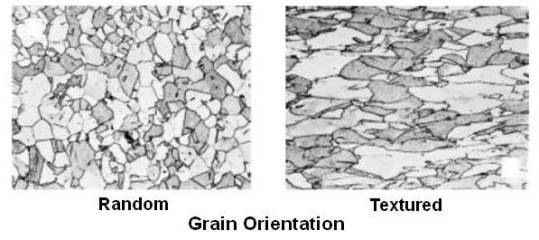
As shown in the above figure if grains are randomly oriented properties will be identical in all directions (isotropic). However, if grains are textured due to working (say rolling), properties will be different in different directions (anisotropic).
