The fracture of a material is dependent upon the forces that exist between the atoms. This theoretical strength due to the forces that exist between the atoms can be calculated. However, the experimentally measured fracture strengths of materials are found to be 10 to 1000 times below this theoretical value. The first explanation for this discrepancy was given by A. A. Griffith in 1921. As per him, this happens due to stress concentration. Information about stress concentration is given in this article.
Stress Concentration
A. A. Griffith theorized that failure in brittle material was caused by many fine elliptical, submicroscopic cracks either on the surface or within the metal. The sharpness at the tip of such cracks will result in a very high stress concentration which may exceed the theoretical fracture strength at this localized area and cause the crack to propagate even when the body of the material is under fairly low applied tensile stress.
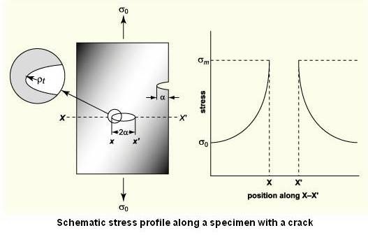
The magnification of the stress at a flaw is dependent upon the orientation and geometry of the flaw. Above figure shows a stress profile across a cross section containing an internal, elliptically-shaped crack. It can be see that the stress is at a maximum at the crack tip and decreased to the nominal applied stress with increasing distance away from the crack. The stress is concentrated around the crack tip or flaw developing the concept of stress concentration.
If the crack is assumed to have an elliptical shape and is oriented with its long axis perpendicular to the applied stress, the maximum stress, σm can be approximated at the crack tip by following equation.
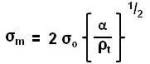
The magnitude of the nominal applied tensile stress is σo, the radius of the curvature of the crack tip is Ït, and α represents the length of a surface crack, or half the length of an internal crack.
The ratio of the maximum stress and the nominal applied tensile stress is denoted as the stress concentration factor K, where K can be calculated by following equation.

The stress concentration factor is a simple measure of the degree to which an external stress is amplified at the tip of a small crack.
Many times during maintenance, a large hole is drilled at the end of the crack. The drilled hole, with its relatively large diameter, causes a smaller stress concentration than the sharp end of a crack. This is however, a temporary solution that must be corrected at the first opportune time.
Fatigue cracks always start at stress raisers, so removing such defects increases the fatigue strength. In many engineering applications where cyclical stressing is critical (like rotating assembly of boiler feed pump and turbine in power generating stations), we must be aware that tiny, sub-critical cracks can grow due to fatigue and become critical leading to fracture.
It is usually possible to detect such defects, using ultrasonic inspection or radiography, to determine the maximum size of defect in the region of interest.
Stress Risers
It is important to note that stress amplification not only occurs on a microscopic level (e.g. small flaws or cracks,) but can also occur on the macroscopic level in the case of sharp corners (key ways), holes, notches (machining flaws) and at abrupt change in cross section.
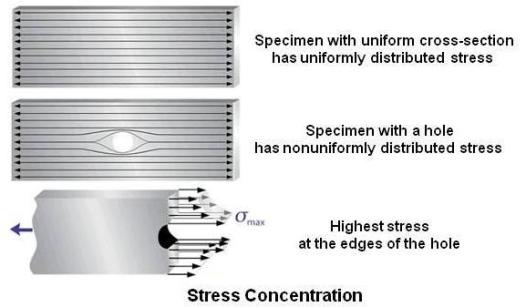
When an axial load is applied to a piece of material with a uniform cross-section, the normal stress will be uniformly distributed over the cross-section. However, if a hole is drilled in the material, the stress distribution will no longer be uniform. Since the material that has been removed from the hole is no longer available to carry any load, the load must be redistributed over the remaining material. It is not redistributed evenly over the entire remaining cross-sectional area but instead will be redistributed in an uneven pattern that is highest at the edges of the hole as shown in above figure.
It can be seen that stress lines are denser near the hole. The location of stress concentration is at the vicinity of the abrupt change in cross section or discontinuity. Because of their ability to amplify an applied stress in their locale, such configurations are called ‘stress raisers’. High local stresses can cause the object to fail more quickly than if it wasn’t there. In view of this, engineers must design the geometry to minimize stress concentrations. To avoid stress concentration, for design of conveyor pulleys in material handling application, many times through shaft with grip locks (shaft with out steps and with out key ways) are used.
The effects of stress raisers are more significant in brittle materials than in ductile materials. In ductile materials, plastic deformation allows a more uniform distribution of the stress in the vicinity of the stress raiser and the resultant stress concentration factors are appreciably less than those in brittle materials.
Programs are available to find stress concentration factors for a given geometry and application. Website address of one such program available on internet at the time of writing this article is http://efatigue.com
Note:
I have not checked the correctness of the program.
