Iron is an allotropic material. The temperature at which the allotropic changes take place in iron is influenced by alloying elements, the most important of which is carbon. Information about the portion of the iron–carbon alloy system which is of interest to engineers, iron–iron carbide equilibrium diagram is given in this article.
The Iron-Iron Carbide Diagram
The part of iron-carbon alloy system diagram between pure iron and an interstitial compound, iron carbide (Fe3C), containing 6.67 percent carbon by weight is called iron-iron carbide equilibrium diagram. It may be noted that though it is called as equilibrium diagram, it is not a true equilibrium diagram, since equilibrium implies no change of phase with time. In fact, the compound iron carbide decomposes into iron and carbon (graphite). This decomposition takes a very long time at room temperature, even at 1300°F, it takes several years to form graphite. The iron carbide is called metastable phase. Therefore, iron-iron carbide diagram even though technically represents metastable conditions, can be considered as representing equilibrium changes, under conditions of relatively slow heating and cooling.

Above figure shows iron-iron carbide equilibrium diagram labeled in general terms with Greek letters to represent the solid solutions. However, it is common practice to give special names to most of the structures that appear on the diagram. The γ solid solution is called austenite. The diagram shows three horizontal lines which indicate isothermal reactions.
The enlarged view of the portion of the diagram in the upper left hand corner is shown in the figure given below.
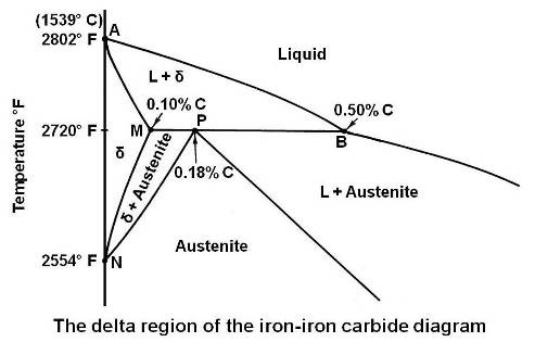
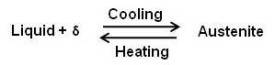
This portion of the diagram is known as delta region because of the δ solid solution. The horizontal line at 2720°F is for a peritectic reaction. The equation for the peritectic reaction may be written as
The maximum solubility of carbon in b.c.c. δ Fe is 0.10 percent at point M. The presence of carbon influences the allotropic change between δ and γ. As the concentration of carbon in iron is increased, the temperature of allotropic change increases from 2554 to 2720°F at 0.1 percent carbon.
On cooling, the line NM represents the beginning of the crystal structure change from b.c.c. δ Fe to f.c.c. γ Fe for alloys containing less than 0.1 percent carbon. The portion MP of line MPB represents beginning of this crystal structure change by means of a peritectic reaction for alloys between 0.10 and 0.18 percent carbon. For alloys containing less than 0.18 percent carbon, on cooling, the end of the crystal structure change is given by the line NP. The portion PB represents the beginning and the end of the crystal structure change by means of the peritectic reaction. That is, for alloys between 0.18 and 0.50 percent carbon, the allotropic change begins and ends at constant temperature. It can be seen that any alloy containing more than 0.5 percent carbon will cut the diagram to the right of point B and will solidify to austenite directly. The delta solid solution and the allotropic change will be completely bypassed.
The figure given below shows the iron-iron carbide equilibrium diagram labeled with the common names for the structures.
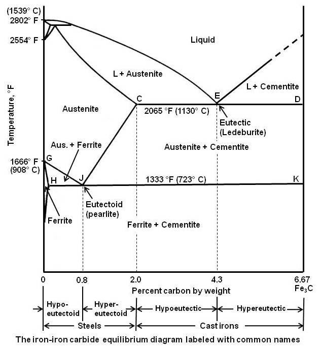
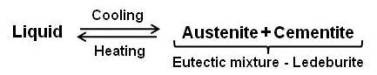
It can be seen that eutectic reaction takes place at 2065°F. The eutectic point E is at 4.3 percent carbon and the line CED is the eutectic temperature line. Whenever an alloy passes this line, eutectic reaction must take place. Any liquid that is present when this line is reached must now solidify into the very fine mixture of the two phases that are at either end of the horizontal line, namely austenite and iron carbide (called cementite). This eutectic mixture is given the name ledeburite, and the reaction may be written as
As shown in the figure, below the eutectoid temperature line HJK, every alloy will consist of a mixture of ferrite and cementite.
Depending on carbon content, it is common practice to divide the iron-iron carbide diagram into two parts. Alloys containing less than 2 percent carbon are known as steels and alloys containing more than 2 percent carbon are known as cast irons. The steel range is further subdivided by the eutectoid carbon content (0.8 percent C). Steels containing less than 0.8 percent C are called hypoeutectoid steels while those containing between 0.8 to 2.0 percent C are called hypereutectoid steels. The cast iron range is also subdivided by eutectic carbon content (4.3 percent C). Cast irons that contain less than 4.3 percent C are known as hypoeutectic cast irons and those containing more than 4.3 percent C are called hypereutectic cast irons.
Micro-constituents/Structures
Names are given to various micro-constituents for descriptive or commemorative reason. Information about them is given below.
Cementite or iron carbide
A fixed amount of carbon and a fixed amount of iron are needed to form cementite. Its chemical formula is Fe3C. It contains 6.67 percent carbon by weight. It is a hard and brittle interstitial compound of low tensile strength (approximately 5000 psi) but high compressive strength. Its crystal structure is orthorhombic. It is the hardest structure that appears on the iron-iron carbide diagram.
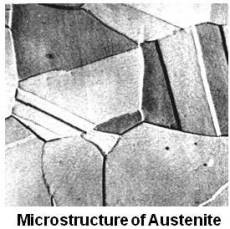
Austenite
Austenite is the name given to the γ solid solution. It is an interstitial solid solution of carbon dissolved in γ iron having a face centered cubic (f.c.c.) crystal structure. Maximum solubility is 2 percent carbon at 2065°F (point C).
Average properties of austenite are as under.
Tensile strength: 150,000 psi
Elongation: 10 % in 2 in. gage length
Hardness: Rockwell C 40
Toughness: High
Austenite is normally unstable at room temperature. Under certain conditions it is possible to obtain austenite at room temperature (as in austenite stainless steels). Austenite is non-magnetic.
Ledeburite
It is the eutectic mixture of austenite and cementite. It contains 4.3 percent carbon and is formed at 2065°F (point E). It exists when the carbon content is greater than 2%, which represents the dividing line on the equilibrium diagram between steel and cast iron.
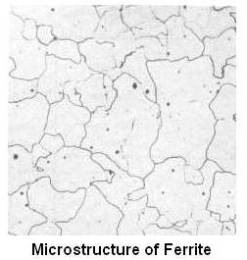
Ferrite
Ferrite is the name given to the α solid solution. It is an interstitial solid solution of a small amount of carbon dissolved in α iron having a body centered cubic (b.c.c.) crystal structure. The maximum solubility is 0.025 percent carbon at 1333°F (point H), and it dissolves only 0.008 percent carbon at room temperature. It is the softest structure on the iron-iron carbide diagram.
Average properties of ferrite are as under.
Tensile Strength: 40,000 psi
Elongation: 40 % in 2 in. gage length
Hardness: Less than Rockwell C 0 or less than Rockwell B 90
Toughness: Low
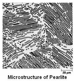
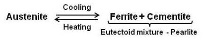
Pearlite
It is the eutectoid mixture containing 0.80 % carbon and is formed at 1333°F on very slow cooling. It is a very fine platelike or lamellar mixture of ferrite and cementite. The structure of pearlite includes a white matrix (ferritic background) which includes thin plates of cementite (black).
Average properties of pearlite are as under.
Tensile Strength: 120,000 psi
Elongation: 20 % in 2 in gage length
Hardness: Rockwell C 20 or BHN 250-300
Pearlite needs fixed amounts of cementite and ferrite.
If enough carbon is not there, that is carbon is less than 0.80 %, the carbon and the iron will combine to form Fe3C until all the carbon is consumed. This cementite will combine with the required amount of ferrite to form pearlite. The remaining amount of ferrite will stay in the structure as free ferrite. Free ferrite is also known as proeutectoid ferrite. The steel that contains proeutectoid ferrite is called hypoeutectoid steel.
If, however, there is an excess of carbon above 0.80% in the austenite, pearlite will form, and the excess carbon above 0.80% will form cementite. The excess cementite deposits in the grain boundaries. This excess cementite is also known as proeutectoid cementite. The steel that contains proeutectoid cementite is called hypereutectoid steel.
Slow Cooling of Steel
The various changes that take place during the very slow cooling from the austenite range for hypoeutectoid steel and hypereutectoid steel are discussed below.
Hypoeutectoid steel
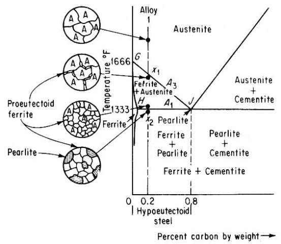
Alloy 1 shown in above figure is a hypoeutectoid steel containing 0.2 percent carbon. In the austenite range it is a uniform interstitial solid solution. Upon slow cooling, nothing happens until the line GJ is crossed at point x1.This line is known as the upper-critical-temperature line on the hypoeutectoid side and is labeled A3.
The allotropic change from f.c.c. to b.c.c. iron takes place at 1666°F for pure iron and decreases in temperature with increasing carbon content, as shown by A3 line. Therefore, at x1, ferrite must begin to form at the austenite grain boundaries. Since ferrite can dissolve very little carbon, in those areas that are changing to ferrite the carbon must come out of solution before the atoms rearrange themselves to b.c.c. The carbon which comes out of solution is dissolved in the remaining austenite, so that, as cooling progresses and the amount of ferrite increases, the remaining austenite becomes richer in carbon. Its carbon content is gradually moving down and to the right along the A3 line. Finally, the line HJ is reached at point x2. This line is called the lower-critical-temperature line on the hypoeutectoid side and is labeled A1. The A1 line is the eutectoid-temperature line and is the lowest temperature at which f.c.c. iron can exist under equilibrium conditions. Just above A1 line, the microstructure consists of approximately 25 percent austenite and 75 percent ferrite. The remaining austenite, about 25 percent of the total material and containing 0.8 percent carbon, now undergoes the eutectoid reaction.
It may be noted that it is only austenite which is changing at A1 line. Therefore, when the reaction is complete the microstructure will show approximately 25 percent Pearlite and 75 percent ferrite.
The changes just described would be the same for any hypoeutectoid steel. The only difference would be in the relative amount of ferrite and pearlite.
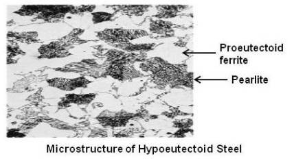
Above figure shows microstructure of a hypoeutectoid steel.
Formation and Growth of Pearlite
At eutectoid point, austenite is an interstitial solid solution having 0.8 percent carbon dissolved in f.c.c. iron. Ferrite, however, is b.c.c. iron and dissolves very little carbon. So, the change in crystal cannot occur until the carbon atoms come out of solution. Therefore, the first step is the precipitation of the carbon atoms to form plates of cementite (iron carbide). In the area immediately adjacent to the cementite plate the iron is depleted of carbon, and the atoms may now rearrange themselves to form b.c.c. ferrite. Thin layers of ferrite are formed on each side of the cementite plate. The process continues by the formation of alternate layers of cementite and ferrite to give the fine fingerprint mixture known as pearlite.
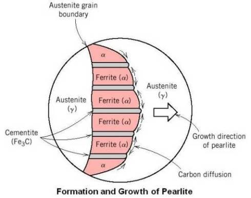
As shown in the above figure, the reaction usually starts at the austenite grain boundary, with the pearlite growing along the boundary and into the grain by nucleation of new cementite and ferrite and growth of existing ferrite and cementite by diffusion of carbon from austenite to cementite.
Hypereutectoid steel
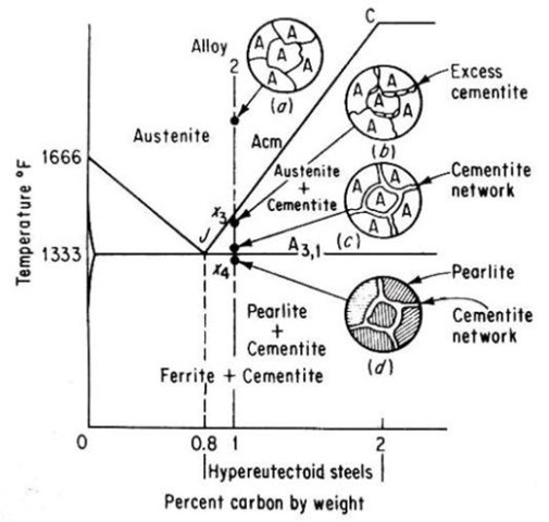
Alloy 2 shown in above figure is a hypereutectoid steel containing 1.0 percent carbon. In the austenite range, this alloy consists of a uniform f.c.c. solid solution with each grain containing 1.0 percent carbon dissolved interstitially. Upon slow cooling, nothing happens until the line CJ is crossed at point x3. This line is called upper-critical-temperature line on the hypereutectoid side and is labeled Acm. The Acm line shows the maximum amount of carbon that can be dissolved in austenite as a function of temperature. Above the Acm line, austenite is an unsaturated solid solution. At the Acm line, point x3, the austenite is saturated in carbon. As the temperature is decreased, the carbon content of the austenite, that is, the maximum amount of carbon that can be dissolved in austenite, moves down along the Acm line towards point J. Therefore, as the temperature decreases from x3 to x4, the excess carbon above the amount required to saturate austenite is precipitated as cementite primarily along the grain boundaries. Finally, the eutectoid line is reached at x4. This line is called the lower-critical-temperature line on the hypereutectoid side and is labeled A3,1. Just above the A3,1 line the microstructure consists largely of austenite, with the excess proeutectoid cementite as a network surrounding the austenite grains. Applying lever rule, the amount of cementite would be
% cementite = [(1.0 – 0.8) / (6.67 – 0.8)] x 100 = 3.4%
And the amount of austenite would be
% austenite = [(6.67 – 1.0) / (6.67 – 0.8)] x 100 = 96.6%
The A3,1 line for Hypereutectoid steels represents the beginning and the end of the allotropic change from f.c.c. austenite to b.c.c. ferrite. The remaining austenite (containing 0.8 percent carbon) transforms to the eutectoid mixture, pearlite.
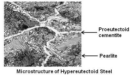
Above figure shows microstructure of a hypereutectoid steel.
The difference in signification of the upper-critical-temperature lines, A3 and Acm may be noted. The line A3 involves an allotropic change where as Acm involves only a change in carbon solubility.
Effect of Carbon on Mechanical Properties of Steel
The mechanical properties of an alloy depend upon the properties of the phases and the way in which these phases are arranged to make up the structure. As was pointed out earlier, ferrite is relatively soft with low tensile strength (40000 psi), while cementite is hard with very low tensile strength (5000 psi). However, the combination of these two phases in the form of the eutectoid (pearlite) produces an alloy of much greater tensile strength (120000 psi) than that of either phase.
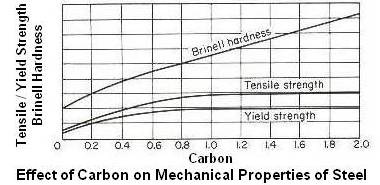
Above figure shows effect of carbon on mechanical properties of hot-worked steel. Since the amount of pearlite increases with an increase in carbon content for hypoeutectoid steels, the strength and Brinell hardness number will also increase up to the eutectoid composition of 0.80 percent carbon. The ductility and impact strength decreases with increasing carbon. Beyond the eutectoid composition, the strength levels off and may even show a decrease due to the brittle cementite network. The Brinell hardness, however, continues to increase due to the greater proportion of hard cementite.
The Critical-temperature Lines.
In iron-iron carbide diagram, upper and lower-critical-temperature lines are shown as single lines under equilibrium conditions and are sometimes labeled as Ae3, Ae1, etc. They are labeled differently because when the critical lines are actually determined, it is found that they do not occur at the same temperature.
The critical line on heating is always higher than the critical line on cooling. To distinguish critical lines on heating from those occurring on cooling, the former are called Ac (c from the French word chauffage, which means heating) and the later Ar (r from the French word refroidissement, which means cooling). Therefore, the upper critical line of a hypoeutectoid steel on heating would be labeled Ac3 and the same line on cooling Ar3.
The rate of heating and cooling has a definite effect on the temperature gap between these lines. The slower the rate of heating and cooling the two lines are nearer to each other, so that with infinitely slow heating and cooling, they would probably occur at exactly the same temperature.
