Socket head cap screws are used for applications with limited space. They have cylindrical head and internal wrenching features (mostly hexagon socket) that allow them to be used in locations where externally wrenched fasteners aren't desirable. They are used for critical vehicle applications, machine tools, tools and dies, earth moving and mining machinery, and a wide range of engineering applications. The most important reasons for the increasing use of socket head cap screws in industry are safety, reliability and economy. In this article information is given on 1936 and 1960-Series socket head cap screws, advantages of socket head cap screws, product and dimensions standards, advantages of Unbrako socket head cap screws, information on metric socket head cap screws made by Unbrako as per ANSI standard and countersunk head screws with hexagon socket.
1936-Series and 1960-Series
This term is generally used in America. The original configuration of socket head cap screws didn't maintain consistent relationships among the nominal shank diameter, head diameter, and socket size throughout the available size range. This limited the performance potential of some sizes. In the 1950s, one socket screw manufacturer in America performed extensive studies to optimize performance based on geometry, fastener material strength, and applications. These studies resulted consistent dimensional relationships throughout the size range. Eventually, these relationships were accepted as industry standards and the year of acceptance – 1960 – was adopted to identify the optimized designs. The term 1936-Series was selected to identify the older style for replacement requirement.
Advantages of socket head cap screws
- As compared to ordinary fasteners, less socket screws of the same size can achieve the same clamping force in a joint.
- As fewer screws are required for a given job, fewer holes are required to be drilled and tapped.
- There is weight reduction as fewer screws are used.
- There will be weight reduction on account of smaller size of the component parts since the cylindrical heads of socket screws need less space than hex heads and require no additional wrench space.
Product and dimensions standards
Product and dimensions standards used for socket head cap screws in various countries are as under.
ANSI: ASTM A574, B 18.3, B 18.3.1M
IS: 2269
ISO: 4762
DIN: 912
BS: 2470, BS-EN ISO 4762
Information on ANSI, IS and ISO standard is given below.
ANSI Standards
As per ANSI, an alloy steel socket head cap screw means a part made in accordance with ASTM A574. The standard requires that dimensions of product shall conform to the requirement of ANSI B 18.3. The finished screws shall have hardness and tensile strength as under.
| Product Size | Hardness, HRC | Tensile Strength, ksi |
|---|---|---|
| 0.5 inch and smaller | 39 to 45 | 180 |
| 0.625 inch and larger | 37 to 45 | 170 |
The standards for metric, alloy steel socket head cap screws, ASTM A574M also specifies one strength level. This strength level is equivalent to ISO 898 Property Class 12.9 and is similar to the strength level for inch socket heads. The dimensions shall be as per ANSI B 18.3.1M.
IS Standards
IS 2269 covers the requirements for hexagon socket head cap screws in the size range M1.6 to M36. They are made as per product grade A (IS 1367, part 2). Their threads shall be metric coarse pitch, 6g as per IS 4218. The nominal dimensions and preferred length-size combination are given in the specification. Their mechanical properties shall be as under.
As per property class 12.9 (IS 1367, part 3) for steel bolts and
As per A2-70 for d ≤ 20 mm and A2-80 for d > 20 mm for stainless steel bolts (IS 1367, part 14).
As per the standard, screw shall be designated by nomenclature, thread size, length, number of the standard and material. Thus a hexagon socket head cap screw of size M12 and length 70 mm and made from steel shall be designated as: Hexagon Socket Head Cap Screw M10 x 70 IS 2269 – steel.
Caution:
Although the ANSI and IS standard specifies only one strength level, metric socket screws are manufactured around the world to various standards. These standards allow strength levels and materials different from the ANSI and IS standard. For example Property Class 6.8 has a nominal tensile strength (600 MPa) only one half of Property Class 12.9 (1,200 MPa). Therefore, there are metric socket screws in distribution that look similar but have different strengths.
Thus the user of metric socket screws must be aware of the strength level of the fasteners he or she is buying. Purchasing by the simple description metric socket head cap screw can result in one of many strength levels being sold. This can result in undesirable product performance.
ISO Standard
Information on ISO standard 4762 is as under.
| Material | Class 12.9 socket cap screws shall be made from an alloy steel which conforms to the following chemical composition requirements– Carbon: 0.20-0.50%; Phosphorous: 0.035% maximum; Sulfur: 0.035% maximum; and one or more of chromium, nickel, molybdenum or vanadium. |
| Heat Treatment | Class 12.9 socket cap screws shall be heat treated by quenching in oil from above the transformation temperature and reheating to a tempering temperature of 380°C minimum. |
| Hardness | Rockwell C 39 – 44 (Vickers HV 385 – 435) |
| Tensile Strength | 1220 N/mm2 minimum. |
| Proof Load | 1100 N/mm2 minimum. |
| Elongation | 8% minimum. |
| Plating | Class 12.9 socket cap screws are usually supplied with a plain, black finish. |
| Note | Class 12.9 socket cap screws are comparable, but not exactly equivalent to U.S. alloy steel socket cap screws. |
Information on dimensions is as under.
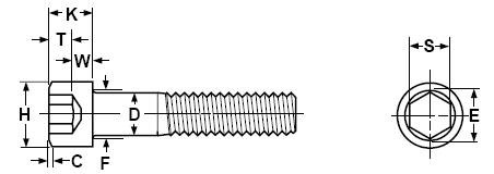
| Basic Screw Diameter | Thread Pitch | D | H | K | C | F | S | E | T | W | ||||
|---|---|---|---|---|---|---|---|---|---|---|---|---|---|---|
| Body Diameter | Head Diameter | Head Height | Top Chamfer or Radius | Fillet Transition Diameter | Socket Size Across the Flats | Socket Size Across the Corners | Key Engage- ment | Wall Thick- ness | ||||||
| Max | Min | Max | Min | Max | Min | Max | Max | Max | Min | Min | Min | Min | ||
| M1.6 | 0.35 | 1.60 | 1.46 | 3.14 | 2.86 | 1.60 | 1.46 | 0.16 | 2 | 1.545 | 1.520 | 1.73 | 0.7 | 0.55 |
| M2 | 0.4 | 2.00 | 1.86 | 3.98 | 3.62 | 2.00 | 1.86 | 0.2 | 2.6 | 1.545 | 1.520 | 1.73 | 1 | 0.55 |
| M2.5 | 0.45 | 2.50 | 2.36 | 4.68 | 4.32 | 2.50 | 2.36 | 0.25 | 3.1 | 2.045 | 2.020 | 2.3 | 1.1 | 0.85 |
| M3 | 0.5 | 3.00 | 2.86 | 5.68 | 5.32 | 3.00 | 2.86 | 0.3 | 3.6 | 2.56 | 2.52 | 2.87 | 1.3 | 1.15 |
| M4 | 0.7 | 4.00 | 3.82 | 7.22 | 6.78 | 4.00 | 3.82 | 0.4 | 4.7 | 3.071 | 3.020 | 3.44 | 2 | 1.4 |
| M5 | 0.8 | 5.00 | 4.82 | 8.72 | 8.28 | 5.00 | 4.82 | 0.5 | 5.7 | 4.084 | 4.020 | 4.58 | 2.5 | 1.9 |
| M6 | 1 | 6.00 | 5.82 | 10.22 | 9.78 | 6.00 | 5.7 | 0.6 | 6.8 | 5.084 | 5.020 | 5.72 | 3 | 2.3 |
| M8 | 1.25 | 8.00 | 7.78 | 13.27 | 12.73 | 8.00 | 7.64 | 0.8 | 9.2 | 6.095 | 6.020 | 6.86 | 4 | 3.3 |
| M10 | 1.5 | 10.00 | 9.78 | 16.27 | 15.73 | 10.00 | 9.64 | 1 | 11.2 | 8.115 | 8.025 | 9.15 | 5 | 4 |
| M12 | 1.75 | 12.00 | 11.73 | 18.27 | 17.73 | 12.00 | 11.57 | 1.2 | 13.7 | 10.115 | 10.025 | 11.43 | 6 | 4.8 |
| M16 | 2 | 16.00 | 15.73 | 24.33 | 23.67 | 16.00 | 15.57 | 1.6 | 17.7 | 14.142 | 14.032 | 16 | 8 | 6.8 |
| M20 | 2.5 | 20.00 | 19.67 | 30.33 | 29.67 | 20.00 | 19.48 | 2 | 22.4 | 17.23 | 17.05 | 19.44 | 10 | 8.6 |
| M24 | 3 | 24.00 | 23.67 | 36.39 | 35.61 | 24.00 | 23.48 | 2.4 | 26.4 | 19.275 | 19.065 | 21.73 | 12 | 10.4 |
| M30 | 3.5 | 30.00 | 29.67 | 45.39 | 44.61 | 30.00 | 29.48 | 3 | 33.4 | 22.275 | 22.065 | 25.15 | 15.5 | 13.1 |
| M36 | 4 | 36.00 | 35.61 | 54.46 | 53.54 | 36.00 | 35.38 | 3.6 | 39.4 | 27.275 | 27.065 | 30.85 | 19 | 15.3 |
| M42 | 4.5 | 42.00 | 41.61 | 63.46 | 62.54 | 42.00 | 41.38 | 4.2 | 45.6 | 32.33 | 32.08 | 36.57 | 24 | 16.3 |
| M48 | 5 | 48.00 | 47.61 | 72.46 | 71.54 | 48.00 | 47.38 | 4.8 | 52.6 | 36.33 | 36.08 | 41.13 | 28 | 17.5 |
| M56 | 5.5 | 56.00 | 55.54 | 84.54 | 83.46 | 56.00 | 55.26 | 5.6 | 63 | 41.33 | 41.08 | 46.83 | 34 | 19 |
| M64 | 6 | 64.00 | 63.54 | 96.54 | 95.46 | 64.00 | 63.26 | 6.4 | 71 | 46.33 | 46.08 | 52.53 | 38 | 22 |
Advantages of Unbrako socket head cap screws
Unbrako has developed and maintained certain manufacturing advantages that continue to set them apart from others. Below is a summary of these advantages.
All socket cap screws have forged heads and hex sockets.
The ASTM A574 (Inch) Specifications and the ASTM A574M (Metric) Specifications mandate cold or hot-formed heads through 1 1/2” or M20 respectively. In all other sizes (sizes above 1 ½” or 20 mm) the specification permits hex sockets to be forged or machined. All unbrako socket cap screw heads and their hex sockets are forged.
All socket cap screws have rolled threads
The ASTM A574 (Inch) Specifications and the ASTM A574M (Metric) Specifications require rolled threads through 5/8” diameter and for screw lengths through 4”, or respectively with metrics requiring rolled threads through M24 diameter, and product lengths up to150 mm inclusive. Larger products may be rolled, cut, or ground at the option of the manufacturer. Ground threads are not produced because of excessive costs. But all Unbrako socket cap screws are roll threaded.
Higher minimum tensile strengths
The ASTM A574 (Inch) Specifications and the ASTM A574M (Metric) Specifications specify minimum tensile strength of 180,000 psi through 1/2”, and 170,000 psi for 5/8” sizes larger, and the appropriate metric equivalents in Mega Pascals The corresponding requirements for core hardness are HRC 39 to 45 for 1/2” or smaller, and HRC 37 to 45 for 5/8” sizes and larger. Unbrako tensile specifications are 10,000 psi higher than standards (1300 or 1250 MPa for metric fasteners) – while maintaining the core hardness range.
Radiused root thread runout
At the beginning of 1966, the thread specification for aircraft fasteners, MIL-S-8879, was released. In Revision A of this spec, it stated that the runout threads must have root radii as large or larger than the normal root radius of the threads. Large radius of runout root provides a smooth form that distributes stress and increases fatigue life of thread run-out. The purpose of this requirement was to strengthen this specific area of the fastener, because this was where most fastener failures occurred. The initial use of this specification was for aircraft fasteners, and while it certainly proved its worthiness in these applications, it has never been added to any commercial fastener standard. However, Unbrako (SPS) saw the merits of this technological advancement, embraced this concept, and developed a Radiused Root Runout as a standard feature on all of their socket cap screws.
“WR” Thread Form
This is an SPS proprietary thread form that fits within the standard UNR thread profile. “WR” stands for WIDE ROOT. This unique thread form has two major differences, and they are both achieved with special thread roll dies made by their Hi-Life Tool division. First, the root of the thread is made as wide as the Unified Screw Thread Series permits. Secondly, they restrict the tolerance of the root radius to the upper, largest 30% of the specification. With this combination, “WR” provides the strongest UNR thread form, and with the greatest opportunity to maximize fatigue resistance.
Etching for thread laps
When threads are rolled onto their products, random samples are being etched in heated acid, and then examined under a stereo microscope to detect thread laps. A thread lap is a flaw. It’s a folding of material when the threads are being rolled. If you don’t check for laps in this method, they’re not likely to be detected. The result will be built-in product defects that then become prime areas to begin fatigue cracking, and then subsequent fastener failures. Because of these efforts, they can certify to ASTM F788, Supplemental Requirement, S1. for Assemblies Subject to Severe Dynamic Stresses on all Unbrako socket cap screws.
Engineered fasteners are often expected to withstand high-fatigue loads or cycles over a prolonged period of time. Above factors and closely controlled manufacturing processes account for the greater fatigue resistance of UNBRAKO socket screws.
Above explains why one shall buy fasteners from a reputed manufacturer. When you buy a product from a reputed manufacturer, you get best quality even without asking it as they are committed to give you best quality product.
Information on ANSI metric socket head cap screws made by Unbrako
For ready reference, information on metric socket head cap screws made by Unbrako as per ANSI standard is reproduced below from Unbrako’s Engineering Guide.
Metric Socket Head Cap Screws as per ANSI Standard
NOTES:
- Material / Applicable or Similar Specification: ASTM A574M / DIN ENISO4762-alloy steel
- Property Class: 12.9-ISO 898/1
- Hardness: Rc 38-43
- Tensile Stress: 1300 MPa thru M16 size and 1250 MPa over M16 size.
- Yield Stress: 1170 MPa thru M16 size and1125 MPa over M16 size.
- Threads: ANSI B1.13M, ISO 261, ISO 262 (coarse series only)
- Thread Class: 4g 6g
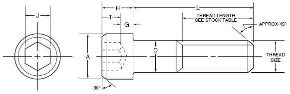
Dimensions, mechanical properties and application data are as under.
| Thread size nom. | Pitch | A max. | D max. | H max. | J nom. | G min. | T min. |
UTS min. MPa | Tensile Strength min. | Single Shear Strength of body min. | Recommended* seating torque, plain finish. | |||
|---|---|---|---|---|---|---|---|---|---|---|---|---|---|---|
| kN | lbs. | kN | lbs. | N-m | in-lbs. | |||||||||
| M1.6 | 0.35 | 3.0 | 1.6 | 1.6 | 1.5 | 0.54 | 0.80 | 1300 | 1.65 | 370 | 1.57 | 352.5 | 0.29 | 2.6 |
| M2 | 0.40 | 3.8 | 2.0 | 2.0 | 1.5 | 0.68 | 1.0 | 1300 | 2.69 | 605 | 2.45 | 550 | 0.60 | 5.3 |
| M2.5 | 0.45 | 4.5 | 2.5 | 2.5 | 2.0 | 0.85 | 1.25 | 1300 | 4.41 | 990 | 3.83 | 860 | 1.21 | 11 |
| M3 | 0.5 | 5.5 | 3.0 | 3.0 | 2.5 | 1.02 | 1.5 | 1300 | 6.54 | 1,470 | 5.5 | 1240 | 2.1 | 19 |
| M4 | 0.7 | 7.0 | 4.0 | 4.0 | 3.0 | 1.52 | 2.0 | 1300 | 11.4 | 2,560 | 9.8 | 2,205 | 4.6 | 41 |
| M5 | 0.8 | 8.5 | 5.0 | 5.0 | 4.0 | 1.90 | 2.5 | 1300 | 18.5 | 4,160 | 15.3 | 3,445 | 9.5 | 85 |
| M6 | 1.0 | 10.0 | 6.0 | 6.0 | 5.0 | 2.28 | 3.0 | 1300 | 26.1 | 5,870 | 22.05 | 4,960 | 16 | 140 |
| M8 | 1.25 | 13.0 | 8.0 | 8.0 | 6.0 | 3.2 | 4.0 | 1300 | 47.6 | 10,700 | 39.2 | 8,800 | 39 | 350 |
| M10 | 1.5 | 16.0 | 10.0 | 10.0 | 8.0 | 4.0 | 5.0 | 1300 | 75.4 | 17,000 | 61 | 13,750 | 77 | 680 |
| M12 | 1.75 | 18.0 | 12.0 | 12.0 | 10.0 | 4.8 | 6.0 | 1300 | 110 | 24,700 | 88 | 19,850 | 135 | 1,200 |
| (M14) | 2.0 | 21.0 | 14.0 | 14.0 | 12.0 | 5.6 | 7.0 | 1300 | 150 | 33,700 | 120 | 27,000 | 215 | 1,900 |
| M16 | 2.0 | 24.0 | 16.0 | 16.0 | 14.0 | 6.4 | 8.0 | 1300 | 204 | 45,900 | 157 | 35,250 | 330 | 2,900 |
| M20 | 2.5 | 30.0 | 20.0 | 20.0 | 17.0 | 8.0 | 10.0 | 1250 | 306 | 68,800 | 235.5 | 53,000 | 650 | 5,750 |
| M24 | 3.0 | 36.0 | 24.0 | 24.0 | 19.0 | 9.6 | 12.0 | 1250 | 441 | 99,100 | 339 | 76,500 | 1100 | 9,700 |
| M30 | 3.5 | 45.0 | 30.0 | 30.0 | 22.0 | 12.0 | 15.0 | 1250 | 701 | 158,000 | 530 | 119,000 | 2250 | 19,900 |
| M36 | 4.0 | 54.0 | 36.0 | 36.0 | 27.0 | 14.4 | 18.0 | 1250 | 1020 | 229,000 | 756 | 171,500 | 3850 | 34,100 |
| M42 | 4.5 | 63.0 | 42.0 | 42.0 | 32.0 | 16.8 | 21.0 | 1250 | 1400 | 315,000 | 1040 | 233,500 | 6270 | 55,580 |
| M48 | 5.0 | 72.0 | 48.0 | 48.0 | 36.0 | 19.2 | 24.0 | 1250 | 1840 | 413,000 | 1355 | 305,000 | 8560 | 75,800 |
|
||||||||||||||
Body and Grip Length dimensions are as under (As per ASME / ANSI B 18.3.1M-1986).
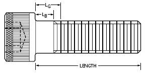
LG is the maximum grip length and is the distance from the bearing surface to the first complete thread.
LB is the minimum body length and is the length of the unthreaded cylindrical portion of the shank.
| Nominal Size | M1.6 | M2 | M2.5 | M3 | M4 | M5 | M6 | M8 | M10 | M12 | M14 | M16 | ||||||||||||
|---|---|---|---|---|---|---|---|---|---|---|---|---|---|---|---|---|---|---|---|---|---|---|---|---|
| Nominal Length | LG | LB | LG | LB | LG | LB | LG | LB | LG | LB | LG | LB | LG | LB | LG | LB | LG | LB | LG | LB | LG | LB | LG | LB |
| 20 | 4.8 | 3.0 | 4.0 | 2.0 | ||||||||||||||||||||
| 25 | 9.8 | 8.0 | 9.0 | 7.0 | 8.0 | 5.7 | 7.0 | 4.5 | ||||||||||||||||
| 30 | 14.8 | 13.0 | 14.0 | 12.0 | 13.0 | 10.7 | 12.0 | 9.5 | 10.0 | 6.5 | ||||||||||||||
| 35 | 19.0 | 17.0 | 18.0 | 15.7 | 17.0 | 14.5 | 15.0 | 11.5 | 13.0 | 9.0 | 11.0 | 6.0 | ||||||||||||
| 40 | 24.0 | 22.0 | 23.0 | 20.7 | 22.0 | 19.5 | 20.0 | 16.5 | 18.0 | 14.0 | 16.0 | 11.0 | ||||||||||||
| 45 | 28.0 | 25.7 | 27.0 | 24.5 | 25.0 | 21.5 | 23.0 | 19.0 | 21.0 | 16.0 | 17.0 | 10.7 | ||||||||||||
| 50 | 33.0 | 30.7 | 32.0 | 29.5 | 30.0 | 26.5 | 28.0 | 24.0 | 26.0 | 21.0 | 22.0 | 15.7 | 18.0 | 10.5 | ||||||||||
| 55 | 37.0 | 34.5 | 35.0 | 31.5 | 33.0 | 29.0 | 31.0 | 26.0 | 27.0 | 20.7 | 23.0 | 15.5 | ||||||||||||
| 60 | 42.0 | 39.5 | 40.0 | 36.5 | 38.0 | 34.0 | 36.0 | 31.0 | 32.0 | 25.7 | 28.0 | 20.5 | 24.0 | 15.2 | ||||||||||
| 65 | 47.0 | 44.5 | 45.0 | 41.5 | 43.0 | 39.0 | 41.0 | 36.0 | 37.0 | 30.7 | 33.0 | 25.5 | 29.0 | 20.2 | 25.0 | 15.0 | ||||||||
| 70 | 50.0 | 46.5 | 48.0 | 44.0 | 46.0 | 41.0 | 42.0 | 35.7 | 38.0 | 30.5 | 34.0 | 25.2 | 30.0 | 20.0 | 26.0 | 16.0 | ||||||||
| 80 | 60.0 | 56.5 | 58.0 | 54.0 | 56.0 | 51.0 | 52.0 | 45.7 | 48.0 | 40.5 | 44.0 | 35.2 | 40.0 | 30.0 | 36.0 | 26.0 | ||||||||
| 90 | 68.0 | 64.0 | 66.0 | 61.0 | 62.0 | 55.7 | 58.0 | 50.5 | 54.0 | 45.2 | 50.0 | 40.0 | 46.0 | 36.0 | ||||||||||
| 100 | 78.0 | 74.0 | 76.0 | 71.0 | 72.0 | 65.7 | 68.0 | 60.5 | 64.0 | 55.2 | 60.0 | 50.0 | 56.0 | 46.0 | ||||||||||
| 110 | 86.0 | 81.0 | 82.0 | 75.7 | 78.0 | 70.5 | 74.0 | 65.2 | 70.0 | 60.0 | 66.0 | 56.0 | ||||||||||||
| 120 | 96.0 | 91.0 | 92.0 | 85.7 | 88.0 | 80.5 | 84.0 | 75.2 | 80.0 | 70.0 | 76.0 | 66.0 | ||||||||||||
| 130 | 102.0 | 95.7 | 98.0 | 90.5 | 94.0 | 85.2 | 90.0 | 80.0 | 86.0 | 76.0 | ||||||||||||||
| 140 | 112.0 | 105.7 | 108.0 | 100.5 | 104.0 | 95.2 | 100.0 | 90.0 | 96.0 | 86.0 | ||||||||||||||
| 150 | 122.0 | 115.7 | 118.0 | 110.5 | 114.0 | 105.2 | 110.0 | 100.0 | 106.0 | 96.0 | ||||||||||||||
| 160 | 132.0 | 125.7 | 128.0 | 120.5 | 124.0 | 115.2 | 120.0 | 110.0 | 116.0 | 106.0 | ||||||||||||||
| 180 | 148.0 | 140.5 | 144.0 | 135.2 | 140.0 | 130.0 | 136.0 | 126.0 | ||||||||||||||||
| 200 | 168.0 | 160.5 | 164.0 | 155.2 | 160.0 | 150.0 | 156.0 | 146.0 | ||||||||||||||||
| 220 | 184.0 | 175.2 | 180.0 | 170.0 | 176.0 | 166.0 | ||||||||||||||||||
| 240 | 204.0 | 195.2 | 200.0 | 190.0 | 196.0 | 186.0 | ||||||||||||||||||
| 260 | 220.0 | 210.0 | 216.0 | 206.0 | ||||||||||||||||||||
| 300 | 256.0 | 246.0 | ||||||||||||||||||||||
Note: For information on length of M20 and M24, please refer web site of Unbrako.
Countersunk head screws with hexagon socket
Countersunk head screws with hexagon socket are widely used for fastening of plates, strips, and other thin sections in modern equipment and machinery requiring strong and reliable joint. They are also known as flat head socket cap screws. Dimensions standards used for countersunk head screws with hexagon socket in various countries are as under.
ANSI: B 18.3, B 18.3.5M
IS: 6761
ISO: 10642
DIN: 7991
BS: 2470, BS-EN ISO 10642
For ready reference information on metric countersunk head screws with hexagon socket made by Unbrako as per ANSI standard is reproduced below from Unbrako’s Engineering Guide.

NOTES:
- Material / Applicable or Similar Specification: ASTM F835M / DIN ENISO10642
- Dimensions: B18.3.5M
- Property Class: 12.9
- Hardness: Rc 38-43 (alloy steel)
- Tensile Stress: 1040MPa
- Shear Stress: 630 MPa
- Yield Stress: 945 MPa
- Sizes: For sizes up to and including M20, head angle shall be 92°/90°. For larger sizes head angle shall be 62°/60°.
- Threads: ANSI B1.13M, ISO 262 (coarse series only)
- Thread Class: 4g 6g
Dimensions and application data are as under.
| Nom. thread size | Pitch | A max. |
D max. |
H ref. |
T min. |
S ref. |
LT min. |
J nom. |
Recommended seating torque* | |
|---|---|---|---|---|---|---|---|---|---|---|
| N-m | in-lbs. | |||||||||
| M3 | 0.5 | 6.72 | 3 | 1.7 | 1.10 | 0.50 | 18 | 2 | 1.2 | 11 |
| M4 | 0.7 | 8.96 | 4 | 2.3 | 1.55 | 0.70 | 20 | 2.5 | 2.8 | 25 |
| M5 | 0.8 | 11.20 | 5 | 2.8 | 2.05 | 0.70 | 22 | 3 | 5.5 | 50 |
| M6 | 1.0 | 13.44 | 6 | 3.3 | 2.25 | 0.85 | 24 | 4 | 9.5 | 85 |
| M8 | 1.25 | 17.92 | 8 | 4.4 | 3.20 | 1.20 | 28 | 5 | 24 | 210 |
| M10 | 1.50 | 22.40 | 10 | 5.5 | 3.80 | 1.50 | 32 | 6 | 47 | 415 |
| M12 | 1.75 | 26.88 | 12 | 6.5 | 4.35 | 1.85 | 36 | 8 | 82 | 725 |
| M16 | 2.00 | 33.60 | 16 | 7.5 | 4.89 | 1.85 | 44 | 10 | 205 | 1800 |
| M20 | 2.50 | 40.32 | 20 | 8.5 | 5.45 | 1.85 | 52 | 12 | 400 | 3550 |
| M24 | 3.00 | 40.42 | 24 | 14.0 | 10.15 | 2.20 | 60 | 14 | 640 | 5650 |
|
||||||||||
For more information on socket head cap screws and related products, please refer to Engineering Guide by Unbrako on their web site: http://www.unbrako.com.au
