Threaded fasteners are tightened to clamp parts together and transmit loads. In gasketed joints, the purpose is to prevent leakage. In other joints, the clamping force is developed to prevent the parts from separating or getting loose and transmit load (e.g. gear couplings). If the fasteners are over tightened, they may break either during the tightening itself or when the working load is added to the pre-load in applications such as gasketed joints. If too loose, the fastener will shake loose in vibration. If they are not adequately tightened, they will be subjected to cyclic loading and fail due to fatigue. Thus proper amount of tightening (pre-loading) is very important. Information about various methods of tightening, sequence of tightening, tightening of stainless steel fasteners and recommended tightening torque values for preloading fasteners is given in this article.
Tightening Methods
In gasketed joints fasteners shall be tightened to create a seal. Thus for this application, one can calculate required pre-load based on internal pressure and number of fasteners. For other applications, required pre-load depends on application and typical values vary from 50% to 80% of the yield strength of the fastener material. For critical applications designer specifies preloading values.
All fastener materials are slightly elastic and must be stretched a small amount to develop clamping force. Within elastic limit, stress is proportional to strain and modulus of elasticity, Young’s modulus (stress / strain = constant) is a property of material. Young’s modulus (tensile or compressive loads) for steel is 30,000,000 psi. Thus for steel fasteners, a stretch of 0.001 inch per inch length of a fastener will develops 30,000 psi clamping force. From this information, one can easily calculate fastener to be stretched for desired pre-load. This method of preloading is very accurate but it requires that the ends of the bolts be properly prepared and also that all measurements be very carefully made. In addition, direct measurements are only possible where both ends of the fastener are available for measurement after installation. Since in most cases it is not possible to measure fastener elongation easily, other indirect methods are used for pre-loading.
Six methods are used to control tightness of a threaded fastener. In order of increasing accuracy they are:
| Method | Accuracy |
| Feel | +/- 35% |
| Torque wrench | +/- 25% |
| Turn-of-the-nut | +/- 15% |
| PLI washers | +/- 10% |
| Bolt elongation | +/- 3 to 5% |
| Strain gages | +/- 1% |
The decision as to which tightening method to use depends primarily on the criticality of the joint. As cost increases with higher accuracy method, generally the method selected will almost always lie between the two extremes. Some applications will allow the high inaccuracy of the "feel" method, while the high cost, highly accurate strain gages are used almost entirely in the laboratory. Information on various methods is as under.
Feel
In this method, fasteners are tightened as per feel of a person based on his work experience. As there is no measurement, quality of work depends on person’s expertise.
Torque wrench
Torque wrench is a manual wrench which incorporates a gauge or other method to indicate the amount of torque transferred to the fastener. In this method, fasteners are tightened by calibrated torque wrench set to a desired torque value.
When torque is applied to a fastener it is used to overcome friction to turn the fastener and stretch the fastener to develop the clamping force. The latter is considered the useful part of the torque. Generally 85% of the torque is used to overcome friction and only 15% is available to produce bolt load. Thus change in the coefficient of friction for different conditions can have a very significant effect on fastener loading. Thus though this is the least expensive and the most popular method for preloading fasteners, it is the least accurate.
Fastener manufacturers usually recommend seating torques for each size and fastener material based on test carried out by them. In absence of information about torque values, the torque tightening equation may be used to decide torque value. Within the elastic range, before permanent stretch is induced, the relationship between torque and tension is essentially linear. Studies have found that there are many variables that have an effect on this relationship. To overcome this, a torque tightening equation (formula) has been developed based on empirical test results as under.
T = KDP Where,
T = torque, Nm (in-pounds).
D = fastener nominal diameter, m (inch)
P = preload, N (pounds)
K = “nut factor,” “tightening factor,” or “k-value”
The nut factor is often assumed to be 0.2 for steel nuts and bolts tightened without lubrication.
More information on friction and nut factor are given in an article reproduced from Loctite, “Torque/Tension Relationship – The Forgotten Factor” at the end of this article.
Turn-of-the-nut
The process of pulling parts of a joint together is called snugging. During snugging most of the input turn is absorbed in the joint with little tension being given to the bolt. The torque required to pull plates together so that direct contact occurs is called snug torque. The snug torque is usually determined experimentally on the actual joint. The snug torque ensures that metal to metal contact occurs at all the interfaces within the joint. At this point the nut or bolt is turned to a predetermined number of degrees in turn-of-the-nut method of tightening. This method also utilizes change in bolt length. In theory, one bolt revolution (360° rotation) should increase the bolt length by the thread pitch. This method is used for slip critical (friction grip) connection of structural members using structural bolts. It eliminates the friction factor. However its accuracy is affected by the care of the workman in measuring the angle the nut or bolt is turned. For more information on this method, please refer article on Structural Bolts.
For using this method with gasket, value of nut or bolt to be rotated after snugging must be developed by tests for each joint because of the "rubberiness" of the joint. The snugging also produces a large variation in preload due to rubberiness of gasket material.
PLI washers
Preload indicating (PLI) washers utilize compression of plastically deformable material of washer under load. The use of load indicating washers is widespread in structural engineering. One type of such washers have small raised pips on their surface which plastically deform as the bolt is tensioned. The correct preload is achieved when a predetermined gap is present between the washer and the under head of the bolt. This is measured using feeler gauges. The smaller the gap, greater is the tension in the bolt. Generally they are not used in mechanical engineering. They are also known as direct tension indicators. For more information on direct tension indicators, please refer – other useful information section in article about Gaskets.
Bolt elongation
Since stress/strain is a constant relationship for any given material, the relationship is used to preload bolt by staining (stretching) it for desired stress (loading). Various methods are used to stretch bolt or measure stretch as the bolt is being loaded. Two such methods used for large size bolts are heat tightening and use of hydraulic tensioner.
Heat Tightening
Heat tightening utilizes the thermal expansion characteristics of the bolt. The bolt is heated to expand. After it has expanded, the nut is indexed (using the angle of turn method) and the system allowed to cool. As the bolt attempts to contract it is constrained longitudinally by the clamped material and a preload results. Methods of heating include direct flame, sheathed heating coil or any other suitable method. This is not a widely used method and is generally used only on very large size bolts.
Hydraulic Tensioner
In this method a hydraulic tool is used to tighten a fastener by stretching it rather than applying a large torque to the nut. After the fastener has been stretched, the nut is run down the thread to snug up with the joint. The hydraulically applied load is then removed resulting in tension being induced into the fastener.
Some times special bolts are used which have provision to measure stretch as they are tightened. One such fastener is the Rotabolt which measures bolt stretch (extension) by the use of a central gauge pin which passes down a centrally drilled hole in the bolt.
Bolt elongation can be measured by ultrasonic measurement also.
Strain gages
By using strain gages, the strain produced can be directly detected. Strain gages may be applied directly to the outside surface of the bolt or by having a hole drilled in the center of the bolt and the strain gage installed internally. The output from these gages need instrumentation to convert the gage electrical measurement method. It is an expensive method and not always practical.
Sequence of tightening
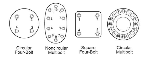
The sequence in which bolts or studs are tightened has a substantial effect on the distribution of preload in a joint. Since in most cases, all bolts of a joint are not tightened simultaneously, tightening of a bolt effects preload in other previously tightened bolts in the group. Such effects are called elastic interaction or bolt cross talk. To minimize this, bolts are tightened in a cross bolt tightening pattern. If the joint is critical it is recommended considering a multiple pass tightening sequence. In such a sequence, each bolt is tightened more than once so as to reduce the preload reduction caused by the tightening of the other bolts in the joint. Tightening of bolts as per tightening sequence uniformly preloads all the bolts of a joint. Always run the nuts or bolts down by hand. This gives an indication that the threads are satisfactory (if the nuts will not run down by hand, then there is probably some thread defect – check again and, if necessary, replace defective parts). Cross bolt tightening sequence for various patterns of joints is shown below.
Tightening of stainless steel fasteners
Stainless steel fasteners can unpredictably sustain galling (cold welding) during preloading. Stainless steel self-generates an oxide surface film for corrosion protection. During fastener tightening, as pressure builds between the thread surfaces, protective oxides are broken, possibly wiped off, and interface metal’s high points and shear or lock together. This cumulative clogging-shearing-locking action causes increasing adhesion. In the extreme case this leads to seizing – the actual freezing together of the threads. If tightening is continued, the fastener can be twisted off or its threads ripped out. The problem can be eliminated by lubricating the threads. In very unfavorable assembling conditions MoS2 or similar lubricants are recommended. It is also recommended to use a very low revolution screw-driving machine or they should be tightened by hand to minimize heat generation during tightening. High temperature increases tendency for galling. Be careful however, if you are using the stainless steel fasteners in food related applications as some lubricants may be unacceptable.
Recommended tightening torque values for preloading fasteners
In case, torque tightening values are not specified, steel fasteners may be preloaded by tightening them to following torque values.
Tightening Torques in Kilograms Meters / Pound Feet
| Grade | Nominal Diameter – Regular Pitch | |||||||||||||||
|---|---|---|---|---|---|---|---|---|---|---|---|---|---|---|---|---|
| M4 | M5 | M6 | M7 | M8 | M10 | M12 | M14 | M16 | M18 | M20 | M22 | M24 | M27 | M30 | ||
| 8.8 | kgm | 0.29 | 0.57 | 1 | 1.6 | 2.5 | 5 | 8 | 13 | 20 | 26 | 36 | 51 | 65 | 98 | 134 |
| Pound Feet | 2 | 4 | 7 | 11 | 18 | 32 | 58 | 94 | 144 | 190 | 260 | 368 | 470 | 707 | 967 | |
| 10.9 | kgm | 0.4 | 0.8 | 1.4 | 2.3 | 3.5 | 6 | 12 | 18 | 27 | 37 | 51 | 72 | 92 | 138 | 188 |
| Pound Feet | 2.9 | 6 | 10 | 16 | 25 | 47 | 83 | 133 | 196 | 269 | 366 | 520 | 664 | 996 | 1357 | |
| 12.9 | kgm | 0.5 | 1 | 1.6 | 2.7 | 4 | 8 | 14 | 22 | 33 | 45 | 61 | 87 | 110 | 167 | 226 |
| Pound Feet | 3.6 | 7 | 11 | 20 | 29 | 58 | 100 | 159 | 235 | 323 | 440 | 628 | 794 | 1205 | 1630 | |
For ready reference tables showing tightening torque and forces for stainless steel fasteners are reproduced below from website of Bufab Stainless AB, Sweden – http://www.bufab-stainless.se
Tigthening torque and forces for A2, A4 and Bumax fasteners
| Thread size and class | Class | M3 | M4 | M5 | M6 | M8 | M10 | M12 | M14 | M16 | M18 | M20 |
| Tigthening Torque Mv in Nm 1), 3) |
Bumax 109 Bumax 88 Bumax Lock 80 70 50 |
1.7 1.3 – 1.2 0.9 0.4 |
4.1 2.9 – 2.7 2 1 |
8.1 5.7 6.6 5.4 4 2 |
14 10 12 9 7 3 |
34 25 29 22 17 8 |
66 47 54 44 33 15 |
115 82 94 76 57 27 |
162 129 – 121 91 43 |
248 198 228 187 140 65 |
344 275 – 261 195 91 |
481 385 442 364 273 127 |
| Preload applied KN ± 23% 2) |
Bumax 109 Bumax 88 Bumax Lock 80 70 50 |
2.9 2.1 – 2.0 1.5 0.8 |
5.2 3.6 – 3.4 2.6 1.4 |
8.6 5.9 – 5.5 4.2 1.9 |
12 8.4 8.4 7.8 5.9 2.7 |
21 15 15 14 11 5 |
34 24 24 23 17 8 |
49 35 35 33 25 12 |
60 48 – 45 34 16 |
81 65 65 61 47 21 |
100 80 – 76 57 27 |
128 102 102 96 72 33 |
| Failure load KN | Bumax 109 Bumax 88 Bumax Lock 80 70 50 |
5 4 – 4 3.5 2.5 |
8.8 7 – 7 6.1 4.4 |
14 11 11 11 9.9 7.1 |
20 16 16 16 14 10 |
37 29 29 29 26 18 |
58 46 46 46 41 29 |
84 67 67 67 59 42 |
115 92 – 92 81 58 |
157 126 126 126 110 79 |
192 154 – 154 134 96 |
245 196 196 196 172 123 |
| Yield Load KN | Bumax 109 Bumax 88 Bumax Lock 80 70 50 |
4.5 3.2 – 3 2.2 1.3 |
8 6 – 5 4 2 |
13 9 9 8 6 3 |
18 13 13 12 9 4 |
33 23 23 22 16 8 |
52 37 37 35 26 12 |
76 54 54 51 38 18 |
92 74 – 69 52 24 |
125 100 100 94 71 33 |
154 123 – 115 86 40 |
196 157 157 147 110 51 |
| Nominal stress area mm² | 5.03 | 8.78 | 14.2 | 20.1 | 36.6 | 58.0 | 84.3 | 115 | 157 | 192 | 245 | |
| Pitch of thread | 0.5 | 0.7 | 0.8 | 1.0 | 1.25 | 1.5 | 1.75 | 2.0 | 2.0 | 2.5 | 2.5 |
| Thread size and class | Class | M24 | M27 | M30 | M36 |
| Tigthening Torque Mv in Nm 1), 3) |
Bumax 88 Bumax Lock 80 70 50 |
665 765 629 472 220 |
961 – 909 682 318 |
1310 – 1240 930 434 |
2280 – 2160 1620 755 |
| Preload applied KN ± 23% 2) |
Bumax 88 Bumax Lock 80 70 50 |
181 181 138 103 48 |
235 – 179 134 63 |
287 – 219 164 77 |
418 – 319 239 112 |
| Failure load KN | Bumax 88 Bumax Lock 80 70 50 |
282 282 282 247 177 |
367 – 367 321 230 |
449 – 449 393 281 |
654 – 654 572 409 |
| Yield Load KN | Bumax 88 Bumax Lock 80 70 50 |
226 226 212 159 74 |
294 – 275 207 96 |
359 – 337 253 118 |
523 – 490 368 172 |
| Nominal stress area mm² | 353 | 459 | 561 | 817 | |
| Pitch of thread | 3.0 | 3.0 | 3.5 | 4.0 |
| Thread size and class | Class | 1/4-20 UNC |
5/16-18 UNC |
3/8-16 UNC |
1/2-13 UNC |
5/8-11 UNC |
3/4-10 UNC |
7/8-9 UNC |
1”-8 UNC |
| Tigthening Torque Mv in Nm 1), 3) |
Bumax 88 80 70 50 |
11.0 10.0 7.7 3.6 |
22.0 21.0 16.0 7.3 |
39.0 37.0 28.0 13.0 |
95.0 89.0 66.0 31.0 |
188.0 175.0 131.0 61.0 |
329.0 308.0 231.0 108.0 |
527.0 493.0 369.0 172.0 |
789.0 737.0 553.0 258.0 |
| Preload applied KN ± 23% 2) |
Bumax 88 80 70 50 |
8.7 8.0 6.0 2.8 |
14.3 13.2 9.9 4.6 |
21.1 19.5 14.6 6.8 |
38.7 35.7 26.8 12.5 |
61.7 56.9 42.7 19.9 |
91.2 84.2 63.2 29.5 |
125.9 116.2 87.2 40.7 |
165.2 152.5 114.4 53.4 |
| Failure load KN | Bumax 88 80 70 50 |
17.0 17.0 14.3 10.2 |
28.0 28.0 23.6 16.9 |
41.5 41.5 35.0 25.0 |
75.9 75.9 64.1 45.7 |
121.0 121.0 102.2 73.0 |
179.0 179.0 151.2 108.0 |
247.0 247.0 208.6 149.0 |
325.0 325.0 273.7 195.5 |
| Yield Load KN | Bumax 88 80 70 50 |
13.1 12.3 9.2 4.3 |
22.4 20.3 15.2 7.1 |
33.2 30.0 22.5 10.5 |
60.8 54.9 41.2 19.2 |
96.9 87.6 65.7 30.7 |
143.4 129.6 97.2 45.4 |
197.9 178.8 134.1 62.6 |
259.6 234.6 175.9 82.1 |
| Nominal stress area mm² | 20.5 | 33.8 | 50.0 | 91.5 | 146.0 | 216.0 | 298.0 | 391.0 |
1) The Mv recommendations refer to burr-free surfaces lubricated with a good quality lubricant.
2) The preload applied is calculated as 65% of Rp 0.2 but in practice the value can be expected to vary between 50 – 80 %
3) The Mv-recommendations are calculated assuming a coefficient of friction of 0.16 which requires a good-quality lubricant.
Hankel Loctite had invented anaerobic technology for thread treatment and gasketing in 1950. They are world leader for anaerobic adhesives sealants and cyanoacrylate adhesives. An article on Torque / Tension relationship from their web site is reproduced below.
Torque/Tension Relationship – The Forgotten Factor
If you have used a torque wrench to ensure correct bolt tension, then you have just become a victim of friction – the forgotten factor. Only by controlling this factor can reliability be restored to the threaded fastener. The correct function of a nut and bolt is to clamp individual parts together with sufficient force, so as to prevent relative movement between the parts. When clamped parts move due to the influence of shock, stress, vibration or thermal forces, structural failures can occur rapidly. The key to reliability then is to prevent relative movement by ensuring that sufficient clamp load is generated in the fasteners. This is best achieved by understanding and controlling the friction forces which absorb so much of the applied torque. Modern design trends using smaller, fewer, high strength/low yield bolts torqued into the yield region, place more and more emphasis on good design practices and understanding of the forces involved. Improper lubrication practices can also lead to many types of failure in bolted assemblies. We tighten a screw or bolt by applying a torque to the head or nut until a balance is obtained between the torque applied and the sum of the bolt tension and friction forces. The distribution of these forces is shown in Table 1.
| TABLE 1 – TORQUE ABSORPTION IN A TIGHTENING BOLT | ||
|---|---|---|
| PERCENTAGE OF TIGHTENING TORQUE | ||
|
COURSE THREAD |
FINE THREAD |
|
|
BOLT TENSION |
15% |
10% |
|
THREAD FRICTION |
39% |
42% |
|
UNDER HEAD FRICTION |
46% |
48% |
|
TOTAL TIGTHENING TORQUE |
100% |
100% |
We see, therefore, that in normal course thread fasteners only 15% of the applied torque actually produces clamp load, the rest is absorbed by friction on the tread flanks and under-head bearing surface of the nut and bolt head.
Modern anaerobic thread-lockers such as Loctite 222, 243, 262 play a major role in improving the reliability of bolted assemblies, not simply by preventing premature loss of clamp load but more importantly, by controlling the friction characteristics of the metal surfaces of the fasteners. Even apparently identical fasteners from the same batch of steel, and having undergone the same heat treatment, can exhibit considerable difference in clamp loads, even when torqued to exactly the same levels. The explanation lies in variations in the “K” factor for the fastener. A simplified model for the relationship between the torque applied, the fastener diameter, the force achieved or required, and the “K” factor is:
T = KDF, where
T = Torque – Nm (inch-pounds)
D = Nominal diameter of fastener – m (inch)
F = Clamp Load – N (pounds)
K = “K” factor. An empirical constant which takes into account friction and the variable diameter under the head and threads where friction is acting (it is not the coefficient of friction, although it is related to it).
Values of “K” can be determined experimentally, see Table 2. The range of values for any lot of fasteners tested was plus or minus 14%, however different fasteners lots increased the variation to plus or minus 20%. The variation in friction (and therefore “K”) is wide since it is the result of extremely high pressures acting on surfaces which vary in roughness, oxide levels, plating finish and thickness, and lubrication types and levels.
Note:
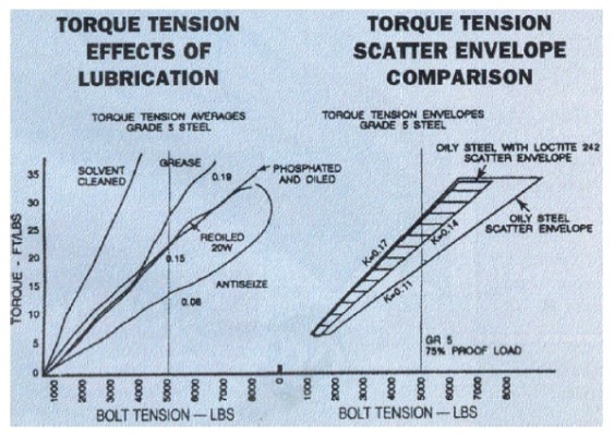
These values were obtained using 16 TPI, 3/8 UNC nuts and bolts, where the bolt was captive and the nut was turned. Both the threads and the nut face were lubricated. An unlubricated thrust face, either nut or bolt head, can almost double the “K” value. The dry solvent cleaned bolt would never achieve the clamp load for which it was designed, irrespective of the amount of torque applied, while the bolt lubricated with anti-seize compound (which is not an uncommon practice with the mining industry and heavy engineering) is stretched well into its elastic limit and is a disaster waiting to happen. The application of the modern anaerobic thread-locking compound Loctite 243 substantially reduces the torque tension scatter envelope over identical “”as received” lightly oiled fasteners.
The “K” factor variation ranging from 0.11 to 0.17 found in seemingly identical fasteners here results in a substantial clamp load variation. At exactly the same torque level of 24 foot pounds, variations between 4500 pounds and 6700 pounds are experienced. This is not exactly a recipe for reliable engineering assembly. The same fasteners treated with Loctite 243 would exhibit a variation between 4700 pounds and 5400 pounds, which is close to the design clamp load for such a fastener when tightened to 75% of its proof load.
| TABLE 2 – TYPICAL "K" VALUES | ||||
|---|---|---|---|---|
|
LIGHTLY OILED |
LIGHTLY OILED |
DEGREASED |
DEGREASED |
|
|
STEEL FASTENER |
0.15 |
0.14 |
0.2 |
0.2 |
|
PHOSPHATED STEEL |
0.13 |
0.11 |
0.24 |
0.14 |
|
CADMIUM PLATED STEEL |
0.14 |
0.13 |
|
|
|
STAINLESS STEEL 404 |
0.22 |
0.17 |
|
|
|
ZINC PLATED STEEL |
0.18 |
0.16 |
|
0.15 |
Clearly, Loctite anaerobic thread-lockers perform a task which is more important than maintaining bolt tension, they provide a reliable means of controlling friction forces so that, once again your torque wrench allows you to achieve the correct tension.
For more information on Loctite and their products, please visit their website – http://www.loctite.com.au
