A wire rope serves as a flexible tackle to transmit pulling force over a distance, to perform hauling, hoisting or suspending operation. Wire ropes and slings find variety of applications in engineering industries, construction and material handling. Information about reasons for use of wire ropes, components of a wire rope, construction of wire ropes, strand patterns, lay and lay selection and wire rope manufacturing process is given in this article.
Why do we use steel wire ropes?
Wire ropes are designed to transmit forces longitudinally along their axis. The reasons for use of wire ropes lie in their three main properties as under.
Strength
Wire rope has very high tensile strength as compared to other types of structural or mechanical systems.
Flexibility
A typical wire rope may contain hundreds of individual wires which are formed and fabricated to move or operate at close bearing tolerances with respect to one another. When a wire rope bends, each of its many wires slides and adjusts in the bend to accommodate the difference in length between the inside and the outside bend. Due to this flexibility, it can be wound on reels or packed in coils resulting into easier storing and transportation. Secondly during use, it can be wound on drums and deflected over sheaves or rollers to change the direction of imparted forces.
Dependability
Safety and dependability of wire ropes are mainly due to its construction in that it consists of many members. Under usual conditions wire ropes give a warning before possible failure by the progressive development of broken wires which can be easily detected by proper inspection. It is therefore possible to replace a wire rope before any unsafe condition is reached. Failure of tensile members such as single wire or rod or linkages of solid units usually takes place instantaneously and completely without any prior warning.
Components of a Wire Rope
A wire rope is generally made up of number of strands twisted around a core. The strands are themselves formed from a number of wires twisted in a helical fashion.
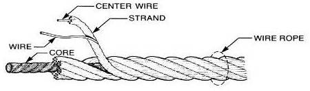
The basic components of a standard wire rope are:
Wires – they form the strand and collectively provide rope strength
Strand – they are laid helically around a core
Core – it forms a seat / foundation for the strands and
Center Wire – it is heart of a strand. It consists of a single wire (known as king wire or core wire) or of fibre.
The wires are predominantly constructed from high-carbon steel, but may also be formed from various metals such as stainless steel, monel or bronze. High-carbon steel wires come in various grades. The term "Grade" is used to designate the strength of the wire rope. Wire ropes are usually made of Improved Plow Steel (IPS), Extra Improved Plow Steel (EIPS) or Extra Extra Improved Plow Steel (EEIPS).
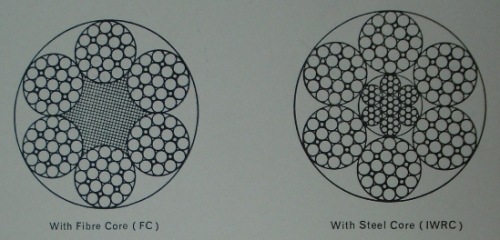
The main function of the core in a wire rope is to serve as a seat for the strands, providing sufficient support and to keep them in their proper position throughout the life of the rope. It is also an effective lubricant carrier. There are two types of core; one is made of fibre and another of wire.
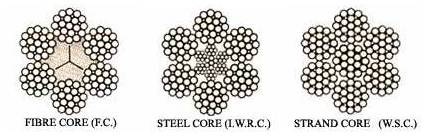
Fibre cores are mainly manufactured from a natural fibre, either manila, sisal or hemp. Present day condition of operation subject a wire rope to severe pressures, and as fibre core ropes will not withstand these condition, their use is restricted to conditions where the loading is light. Some fibre cores are manufactured from polypropylene or nylon but the use of synthetic fibre cores has been confined to a few types of service where they are able to stand up to chemical agents which would attack a natural fibre.
Cores made from wire are usually a small wire rope of suitable size to serve as a core. This is called an independent wire rope core, usually referred to as IWRC. The other type of wire core is a wire strand structure. It is called a strand core and usually abbreviated as WSS (wire strand structure) or WSC (wire strand core). The IWRC is preferred as a core where resistance to crushing or heat is required.
Wire Rope Constructions
In describing the construction of a wire rope the details are normally given in the following order.
- The number of strands.
- The number of wires per strand. Frequently, in the case of Flattened Strand, the number of wires in each layer of the strand is detailed and in Round Strand, the make-up is named, e.g. Seale, Filler, and Warrington.
- The number of fibre centers plus fibre core or description of steel core.
- Whether Round Strand or Flattened Strand.
Examples:
6X37/1 = 6 strands each of 37 wires laid round one main fibre core.
6X12/7 = 6 strands each of 12 wires over one fibre centre laid round one fibre core.
6X19XIWRC = 6 strands each of 19 wires laid round an independent wire rope core.
6X61XWSC = 6 strands each of 61 wires laid round a steel strand core.
6X10 (7 over 3) FS = 6 strands each of 10 wires laid 7 over 3, laid round one fibre core, flattened strand.
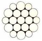
Wire rope construction is also described by a picture of wire rope cross section showing wires and their arrangement.
Example:
Above picture shows cross section of wire rope having 6X19 (12/6+6F/1) construction.
Description of Rope Construction as per British Standards Institution
The number of strands in a rope is separated from the composition of each strand by the multiplication sign “X“.
Example:
6X37 = A rope of 6 strands with 37 wires in each strand.
The number of wires in each layer of wires in a strand is separated by the oblique sign “/“.
Example:
6X18/12/6/1 = A rope with 6 strands, each strand consisting of a layer of 18 wires over a layer of 12 wires over a layer of 6 wires over 1 wire.
In Filler Construction the number of filler wires added to a layer of ordinary wires is indicated by the plus sign “+“ followed by capital letter “F“.
Example:
6X12/6+6F/1 = A rope of 6 strands, each strand consisting of a layer of 12 wires over a layer comprising 6 ordinary and 6 filler wires over 1 wire.
Layers of pairs of large and smaller wires as in Warrington Construction are symbolized by the word “and“.
Example:
6X18/6 and 6/6/1 = A rope of 6 strands, each strand consisting of a layer of 18 wires over a layer comprising of 6 large and 6 small wires over a layer of 6 wires over 1 wire.
Strand Patterns
Strand patterns refer to different types of arrangements of wires and their diameters within a strand. Different strand patterns are as under.
Round Strand
The wires and strands are round in formation.
Centreless Strand
In this strand there is no centre. All the wires are of equal size and are twisted to assume a helical shape.
Single Layer Strand
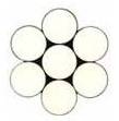
In this design, the outer wires are wound around a centre wire.
Multiple Layer Strand
In this design, strands are made in more than one operation (For example, 19 wire strand is produced in two operations. In first operation, single layer strand is made. Another layer of 12 outer wires is laid on the first layer in the second operation.). The layers are formed one over the other in succession.
If wires of equal size are used in all layers, it will be necessary to change the lay (or pitch) of the covering layer to that of the covered layer so that the wires would fit in smoothly and the wires will be cross laid. If wires are to be laid parallel (having same length of lay in all layers), different size of wires will be required in different layers (as in seale or warrington strand) or filler wires will be required to be filled in between the two layers (as in filler strand).
Seale Strand
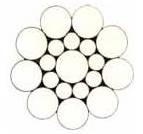
In this design, the outer layer has a predetermined number of large wires. They are laid around an equal number of small inner wires in such a manner that the outer wires lie in the valley of the under lying wires. The advantage of this form is in its more abrasive surface.
Filler Strand
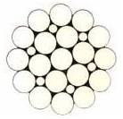
In this design, in each valley between two layers a small wire is filled. The advantage of this construction is in its greater strength.
Warrington Strand
In this design, a layer of pairs of wires (one large and one small) is laid over an inner layer of wires. The number of wires in the inner layer is half of those in the outer layer. In this formation the strand is more roundish. It has more wearing surface without losing flexibility.
Combination Strand
In many compound constructions, when there are more than two layers of wire over the centre wire, a combination of any two from among Filler, Seale and Warrington is designed.
Example:
In the Warrington Seale construction shown in above figure, the intermediate layer has a Warrington relationship with the inner layer and a Seal relationship with the outer.
Flattened Strand
The cores of the strands of a flattened strand rope may consist of one or more triangular wire or three or more round wires. The strands may be triangular or oval.
Above picture shows cross section of a triangular strand. Three round wires are forming core of the strand. Flattened strand have greater surface area of steel. The Flattened Strand rope have about 15% greater cross sectional metallic area, hence they are stronger and have longer life. They are mainly used in the mining industry as haulage rope.
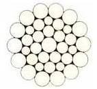
Compact Strand
If a strand is made by compacting wires, it is called compact strand. To make compact strands, ready made strands are forced through a series of rollers which compress the strand and shape the individual wires to have a flat outer surface.

Above figure shows cross section of a 6X26 (1/5/5+5/10) Warrington – Seale pattern compact strand wire rope. The compacting process provides increased strength and durability. The smooth surface inherently provides a high resistance to abrasion and crushing improving service life of the rope.
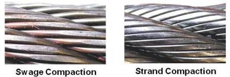
Swage Compaction
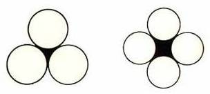
This process is usually applied to wire ropes with plastic coated core. This process is applied after the rope has been manufactured and compresses the entire rope circumference. Due to the process, individual surface wires are shaped flat and strand gaps are closed. The process transforms the entire rope into a more 'round' shape as shown below (pictures of strand compaction is also given for comparison).
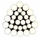
Rotation Resistant Rope
When loaded, steel wire rope generates torque at ends if both ends are fixed and turns if one end is unrestrained (for example anchored using a swivel). Rotation Resistant ropes ensure that problems associated with load rotation are minimized. Rotation resistant ropes are constructed with 2 or more layers of opposite twisted strands

Above figure shows19X7 wire rope designed to resist the tendency to spin or rotate under load. This is achieved by laying 6 strands around the core in one direction and then laying 12 strands around the first layer in another direction. If outer strands are NOT twisted in the opposite direction, the rope will not be rotation resistant. They are often used for hoisting unguided loads with a single part rope.
Two layer ropes have a larger tendency to rotate than three layer ones (e.g. class 34×7). Furthermore, two layer rotation resistant ropes will develop only about 55% to 75% of their breaking strength when one end is allowed to rotate freely. This number increases to between 95% to 100% for three layer rotation resistant ropes.
Locked Coil Ropes
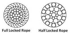
These ropes have a smooth cylindrical surface. The outer wires of the rope are drawn to such shape that each one interlocks with its adjacent wire. The wires are disposed in concentric layers above a wire core instead of strands. They are used for material handling and mining application.
Lay and Lay Selection
Wire ropes are made in either Regular (Ordinary) Lay or Lang’s Lay. Information about lay and its selection is as under.
Lay
Lay is the direction (hand of lay) and length of the twist (length of lay) of wires in a strand and of the strands forming a wire rope.
Length of Lay
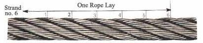
Each strand in a wire rope is helical in shape. The distance measured parallel to the axis or the centre line of a rope in which the strand makes one complete spiral around the rope is the length of rope lay.
The length of the helix of the individual wires in the strands is referred to as strand lay. This length is measured in the same manner as rope lay.
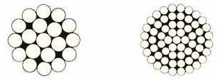
Hand of Lay
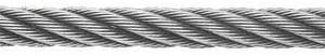
This term refers to the direction in which the strands are laid up in the rope. Left hand lay or right hand lay describe the manner in which the strands are laid to form the rope. To determine the lay of strands in the rope, a viewer looks at the rope as it points away from them. If the strands appear to turn in a clockwise direction, or like a right hand thread, as the strands progress away from the viewer, the rope has a right hand lay. The above picture of steel wire rope shows a rope with right hand lay. If the strands appear to turn in an anti-clockwise direction, or like a left hand thread, as the strands progress away from the viewer, the rope has a left hand lay.
Regular Lay or Ordinary Lay
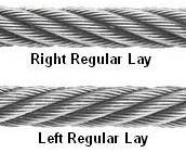
In regular lay wires in each strand is in the opposite direction to the lay of the strands that form the rope. It is also known as ordinary lay. The wires in regular lay rope appear to be in line with the axis of the rope.
Lang’s Lay
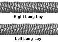
In Lang’s lay wires in each strand is in the same direction as the lay of the strands that form the rope. This lay is also known as Albert’s lay.
“Cross Laid” and “Equal Laid” Principle
Cross laid construction is usually one size wire construction where all the wires, except the King or Centre Wire, are of the same diameter. In the stranding operation each covering layer is provided with a longer lay (or pitch) than the underlaid layer of wires. Therefore, in cross laid ropes, the wires in the covering layer, although spiraling in the same direction as the wires in the underlaid, will repeatedly cross over the inner wires.
The equal (parallel) laid principle is to make each covering layer of wires to the same length of lay as the underlying layer, thereby eliminating any crossing of the wires in these strands. Seale, Filler and Warrington strand forms are examples of equal laid principle.
Lay Selection
A standard wire rope is a right hand regular lay rope composed of six strands laid around a core. All ropes are supplied with this lay unless otherwise specified.
Left hand regular lay ropes are used where drum and anchorages are such that right lay ropes wound under load would tend to roll away from adjacent laps, resulting in uneven winding. They are also used to counter the rotation of a right hand lay rope when two ropes are used as a pair. Usually, a left hand lay rope is used in combination with a right hand lay rope. Left hand lay is also used in ropes for drilling purposes to prevent unscrewing of rods.
Regular / Ordinary lay ropes are suitable for all general work.
Lang’s lay ropes are used in construction and mining applications. It is more flexible and has greater abrasion resistance due to longer length of wire exposed to wear than ordinary lay rope. Since Lang’s lay ropes have little resistance within themselves (to unlaying) on account of the wires and strands being laid in the same direction, they should not be used where the load is suspended from a free end and allowing the rope to rotate. When a Lang’s lay rope is unwound care should be taken since it has got tendency of unlaying.
A six strand wire rope in which three strands are ordinary lay and three strands are Lang’s lay is known as alternate lay wire rope and combines some desirable properties of both the regular lay and the Lang’s lay type of rope.
The use of equal (parallel) lay strands avoids deformation, internal wear and secondary bending which results from the point of contact between the wires in a cross laid strand. In most fields of application, therefore, equal lay ropes have proved to have a longer life than cross laid ropes.
Wire Rope Manufacturing Process
Various operations carried out for making wire ropes are as under.
Patenting (Heat Treatment)
Steel wire ropes are made from high carbon Steel rods. Patenting is a heat treatment process. In patenting wire rods are heat treated above their transformation temperature. Due to this they attain a homogeneous granular structure.
Pickling (Descaling)
After patenting oxide forms on the surface of rod / wire. This oxide is removed from rod/wire by immersing them in a tank of cold hydrochloric acid, rinsing thoroughly with a jet of water, and finally covering the surface with a layer of protective phosphate coating.
Drawing
It is a cold process involving plastic deformation of steel. In drawing, preheated and pickled rod is cold drawn through a series of successively smaller, accurately shaped and polished dies. After drawing, the material now in wire form acquires its final mechanical properties, shape and size
Galvanizing (Zinc Coating)
Galvanizing is a means of protecting steel against corrosion by coating it with Zinc (spelter). The coating of Zinc is normally applied by the Hot Dip process or by electro-depositing. In Hot Dip process the finished drawn wire is passed through a bath of molten zinc. Galvanized wires made by Hot Dip process are not suitable for high tensile strength application as the bath temperature is sufficiently high to alter the physical and mechanical characteristics. In coating by Hot Dip or electro-depositing, the coating of spelter on wire tends to be porous and also liable to cracking or flaking.
If high tensile strength is required, wires are drawn after galvanizing. They are called "Drawn Galvanized". Due to drawing after coating, the spelter becomes more homogeneous and is bonded to the steel much more firmly. This method produces wires having desirable properties of a bright wire (uncoated wires are called "bright" or "black") with a corrosion resisting Zinc coat.
"Drawn Galvanized" wire has the same strength as bright wire, but wire, "galvanized at finished size" is usually 10% lower in strength.
Standing ropes, such as rigging for ships, guy ropes, bridge ropes, etc., which are exposed to the atmosphere and often a corrosive atmosphere, are normally galvanized, or fully galvanized, i.e. made from wires in the state it comes from the galvanizing process without further treatment. This ensures a heavy coating of spelter and gives maximum protection.
On operative ropes, however, such as hoisting ropes, crane ropes, etc., Drawn Galvanized wires are used. The wire used in the manufacture of the rope in this instant is drawn after the wire is galvanized. This reduces to a degree the amount of spelter per sq. mm. of wire but bonds the spelter to the wire more firmly than in the case of fully galvanized wire. This is essential when the rope is working over pulleys or drums.
Winding
Finished wires after drawing / galvanizing are wound onto bobbins to be fed into stranding machines.
Stranding
In stranding, predetermined number of wires are helically laid around a center to make a strand.
Closing (Roping)
In closing predetermined number of strands (generally six) are laid helically around a core (fibre or steel) to make steel wire rope.
Performing
Performing is the process in which each individual strand and each individual wire is permanently formed (shaped or set) during fabrication process in the helical shape it will assume in the finished wire rope. This process causes the strands to lie in place and removes the tendency of wires and strands to fly apart when cut. As performed rope is more inert than non performed rope, it is easier to handle during installation and is less susceptible to the formation of kinks. It can be put to work at full capacity after a shorter “running in” period.
Outer wires of preformed ropes after breaking do not protrude from the rope to injure workmen’s hands, do not distort adjacent wires or cause excessive wear to sheaves and drums.
Usually, a general engineering rope is preformed, whereas an elevator rope is non-preformed.
Postforming
When required, ropes are subjected to postforming in addition to the aforesaid performing process, where the residual stress resulting out of the stranding and closing operations are minimized and the rope becomes “dead”.
Pre-stretching
Wire ropes for certain uses as in suspension bridge should not elongate while in use. So, after manufacture, the whole length of the wire rope is per-stretched to prevent further elongation. This is done by fixing the ends of the wire rope at two terminal and applying safe working load for a certain period of time as per specification. As a result of this, the structural and elastic stretch that may arise during the valuable life of the rope is done away with.
For more information on pre-stretching, please refer IS 9282: Wire ropes and strands for suspension bridges.
Rope Dressing (Lubrication)
Lubrication of ropes serves a double purpose. Firstly the lubrication resists corrosion and secondly, it enables the wires to move in smoothly resulting in less wear.
During the process of manufacture the strands of the core are well lubricated. In case of ropes for general use the fibre core is thoroughly impregnated with suitable lubricants which prevent the fibre core from wroughting and also act as a preservative of lubricant providing internal lubrication.
Finally, the rope itself is passed through a bath of a special wire rope dressing compound which thoroughly lubricates the rope and also leaves a thin film of lubricant on the surface of the wire rope. The rope thus lubricated, permits strands and wires to move smoothly and is preserved against corrosion during the time of transport and storage.
Testing
For quality control, testing is carried out at various stages of manufacturing like raw material testing, testing for thickness of Zinc coating after galvanizing, testing of finished wires for shape and size (diameter, roundness in case of round wires, and smoothness) before stranding and testing of wire ropes after closing operation to destructive test or proof load test as per requirement.
