Performance of wire rope in a machine is affected by design of its sheaves and drums. Information about design of sheave and drum (diameter, the shape of the groove profiles and corresponding radius, the drum pitch and the fleet angle) is given in this article. Other useful technical information on wire ropes – measurement of diameter; generally accepted design factors; capacity of drums and reels; reserve strength; wire rope clips and wire rope end connections is also given in this article.
Sheave and Drum Design
Sheave and drum design factors affecting life / performance of a wire rope are as under.
Sheave and Drum Diameters
Rope breaking strength is determined in a standard test wherein fittings are attached to the ends of the rope and the rope is pulled in a straight line. If however, the rope passes over a curved surface (such as a sheave or pin) its strength is decreased. The amount of such reduction will depend on the severity of the bend as expressed by the D/d ratio where D is sheave / drum diameter and d is wire rope diameter. At smaller D/d ratios, the loss in strength increases quite rapidly.
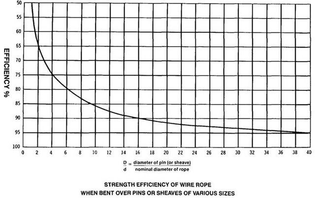
The above graph shows strength efficiency of wire rope when bent over pins or sheaves of various sizes.
It can be seen that, a rope bent around a pin of its own diameter will have only 50% of the strength attributed to it in the standard test. This is called '50% efficiency'. Even at D/d ratios of 40, there may be a loss of up to 5%.
In view of above, relevant standard or statutory requirement shall be followed. In absence of such requirements, the diameter of drum or sheave shall not be less than that given in the table below.
| Purpose | Construction | Minimum D/d Ratio |
|---|---|---|
| Colliery winding | 6×6/1 | 90 |
| 6×12/6/1 | 70 | |
| Colliery haulage | 6×6/1 | 70 |
| Lifts and hoists | 6×12/6/1 | 40 |
| 6×12/6+6F/1 | 40 | |
| 6×9/9/1 | 50 | |
| 8×12/6/1 | 32 | |
| 8×9/9/1 | 40 | |
| General engineering applications | 6×6/1 | 40 |
| 6×12/6/1 | 25 | |
| 6×18/12/6/1 | 20 | |
| 6×61 | 17 |
Groove Dimensions
It is necessary to have radius of the groove to be slightly larger than that of the rope passing over it.
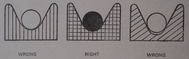
A too narrow groove will crush the rope and damage the wires soon. In too wide groove, the rope will wear more quickly at the point of contact and also cut a false groove in the pulley. In wide groove, the rope will not have lateral support and it will flatten under load. A rope shall be supported by the groove for one third of its circumference. Recommended groove dimensions for sheave and drum are as under.
Groove Dimensions for a Sheave
Recommended dimensions for radius, depth and throat angles are as under.
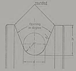
Groove radius (r): Minimum = 0.53 to 0.535 x d and Maximum = 0.55 x d
Groove depth (h): 1.5 x d
Throat angle: 35° to 45° (For normal applications)
Groove Dimensions for a Drum
Recommended dimensions for radius, depth and pitch are as under.
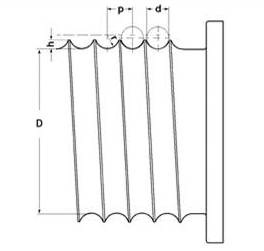
Groove radius (r): Minimum = 0.53 to 0.535 x d and Maximum = 0.55 x d
Groove depth (h): Minimum h ≥ 0.374 x d for helically grooved drums.
Pitch (p): The pitch shall not be smaller than 2.065 x groove radius and larger than 2.18 x groove radius.
Sheave and Drum Design as per IS 3177
IS 3177 is a code of practice for electric overhead travelling cranes and gantry cranes other than steel works crane.
The cranes are designed for four mechanism classes (Class 1 to 4) based on different duty factors (for strength and wear) and average life (running time per day and total life). For more information on various terms, please refer the specification.
Various dimensions as per the specification shall be as under.
D/d Ratio for Drums and Sheaves
| Rope Construction | D/d Ratio based on Mechanism Class |
|---|---|
| 6×19 | 23 to 29 |
| 6×24, 6×36 and 6×37 group multi-strand | 17 to 22 |
Radius of Groove in Drums and Sheaves
| Diameter of Rope in mm | Increase over Rope Radius in mm |
|---|---|
| Up to and including 16 | 1.0 |
| Over 16 and including 24 | 1.5 |
| Over 24 and including 28 | 2.0 |
| Over 28 | 3.0 |
Grooving of Drums
The contour at the bottom of the grooves shall be circular over an angle of approximately 120 degrees. The depth of the groove shall be not less than 0.35 times the diameter of the rope. The grooves of the drum shall be so pitched that there is, between adjacent turns of the rope, a clearance of not less than:
- 1.5 mm for ropes up to and including 12 mm diameter,
- 2.5 mm for ropes over 14 mm and including 8 mm diameter, and
- 3.0 mm for ropes over 28 mm diameter.
Grooving of Sheaves
Sheaves shall be grooved to a depth of not less than 1.5 times the diameter of the rope. The contour at the bottom of the grooves shall be circular over an angle of approximately 130 degrees.
Fleet Angle
Where a wire rope leads over a sheave and on to a drum, the rope will not remain in alignment with the sheave but will deviate to either side depending on the width of the drum and the distance from the fixed sheave.
The fleet angle is the angle created at the point of intersection of a line drawn from the inside edge of the drum flange and along the centre line of the rope lead, and a line drawn from the centre of the drum at right angle to it. This angle is formed at the lead pulley. On a crane fitted with a grooved drum the angle should never exceed 4 degree and on a crane fitted with a flat-faced drum the angle should be between ½ degree and 2 degree maximum. If this angle is more, there will be heavy wear of the rope and groove sides.
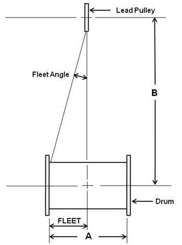
To ensure the correct fleet angle, the following formula may be useful in finding the height of the lead pulley or the width of the drum, when one of these two measurements is known.
C = A/B where,
C = Constant having maximum value as under.
C = 0.07 for flat faced drums and
C = 0.14 for grooved drums.
As per IS 3177, fleet angle shall not exceed 5 degrees.
Diameter of a Wire Rope
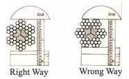
Diameter of a wire rope is the diameter of a circle circumscribing the strands. Care should be taken to see that it is measured correctly as shown above. The actual diameter usually varies from the nominal diameter of a rope. As per IS 2266, actual diameter can vary by -1% to 4 % of the nominal diameter of the rope.
When measuring the rope diameter, don't measure the layer on the reel. Measure the rope when it is straight. To find the correct diameter at a point in a rope, the callipers must be placed over each pair of opposite strands, i.e. three separate readings for a six strand rope. The readings are then averaged.
The rope you are going to replace may be worn out and may measure less than the new rope. Measurement of rope to know its size shall be carried out where it is not worn out.
Generally accepted design factors for various purposes (type of services)
| Generally Accepted Design Factors | |
|---|---|
| Purpose (Type of Service) | Minimum Design Factor |
| Fixed guys, Derricks, Jib cranes, etc. | 4.0 |
| General Engineering, slings, etc. | 5.0 |
| Hot Ladle Cranes | 8.0 |
| Mining ropes | 10.0 or other figure laid down by statutory authority. |
| Passengers and goods lifts and hoists. Rope speed not exceeding 120 m / min. |
10.0 |
| Passengers and goods lifts and hoists. Rope speed not exceeding 210 m / min. |
11.0 |
| Passengers and goods lifts and hoists. Rope speed not exceeding 425 m / min. |
12.0 |
Capacity of Drums / Reels
The following formula and table are a convenient method of calculating how long wire rope a drum or reel will hold.
Capacity of reel in feet or meters = (A+B) x A x C x K
Where,
A = Depth of rope space in inches or mm
B = Diameter of drum in inches or mm
C = Width of drum between flanges in inches or mm
K = π / 12 D2 when capacity is required in feet
K = π / 1000 D2 when capacity is required in meters
K = Constant for a given wire rope diameter (As per table below) and
D = Rope diameter in inches or mm
Table for value of constant
| Rope Diameter | Value of Constant for | ||
|---|---|---|---|
| Inch | mm | Feet | Meters |
| 1/4 | 6 | 4.19 | 0.00009 |
| 3/8 | 9 | 1.85 | 0.00004 |
| 1/2 | 13 | 1.05 | 0.00002 |
| 5/8 | 16 | 0.670 | 0.000012 |
| 3/4 | 19 | 0.465 | 0.000008 |
| 7/8 | 22 | 0.342 | 0.000006 |
| 1 | 25 | 0.262 | 0.000005 |
| 1 1/8 | 29 | 0.207 | 0.000004 |
| 1 1/4 | 32 | 0.168 | 0.000003 |
| 1 1/2 | 38 | 0.116 | 0.000002 |
| 1 3/4 | 43 | 0.085 | 0.000001 |
Reserve Strength
The reserve strength of a wire rope is the strength of the rope exclusive of the outer layer of wires, which are damaged. Following are the approximate reserve strengths expressed as a percentage of the total strengths of well lubricated new ropes.
| Construction | Percentage of Total | |||
|---|---|---|---|---|
| Fibre Core | Steel Core | |||
| Outer Wires | Inner Wires (Reserve Strength) |
Outer Wires | Inner Wires (Reserve Strength) |
|
| 6×7 – 6×6/1 | 84 | 16 | 71 | 29 |
| 6×19 Group | ||||
| 6×19 – 6×12/6/1 | 63 | 37 | 54 | 46 |
| 6×19 – 6×9/9/1 | 66 | 34 | 57 | 43 |
| 6×16 – 6×10/5+5F/1 | 63 | 37 | 54 | 46 |
| 6×19 – 6×12/6+6F/1 | 55 | 45 | 47 | 53 |
| 6×19 – 6×6 and 6/6/1 | 59 | 41 | 52 | 48 |
| 6×37 Group | ||||
| 6×37 – 6×18/12/6/1 | 48 | 52 | 41 | 59 |
| 6×29 – 6×14/7+7F/7/1 | 50 | 50 | 43 | 57 |
| 6×31 – 6×16/8+8F/6/1 | 49 | 51 | 42 | 58 |
| 6×37 – 6×15/15/6/1 | 50 | 50 | 43 | 57 |
| 6×41 – 6×16/8 and 8/8/1 | 48 | 52 | 56 | 44 |
| 6×36 – 6×14/7 and 7/7/1 | 50 | 50 | 43 | 57 |
| 8×19 Group | ||||
| 8×19 – 8×12/6/1 | 63 | 37 | 48 | 52 |
| 8×19 – 8×9/9/1 | 66 | 34 | 51 | 49 |
| 8×16 – 8×10/5+5F/1 | 63 | 37 | 47 | 53 |
| 8×19 – 8×12/6+6F/1 | 55 | 45 | 42 | 58 |
| 8×19 – 8×6 and 6/6/1 | 59 | 41 | 44 | 56 |
| Others | ||||
| 6×12 – 6×12/ F.C. | 100 | - | - | - |
| 6×24 – 6×15/9/F.C. | 63 | 37 | - | - |
| 17×7 – 11/6×6/1 | 55 | 45 | 52 | 48 |
| 18×6 – 12/6×6/1 | 57 | 43 | 54 | 46 |
Wire Rope Clips
Wire rope clips serve as an alternative to splicing and are a simple mechanical means of securing a wire rope round a thimble. They are also known as Bulldog Clips.
Wire rope clips are made from two types of materials. They are malleable iron and drop forged steel. Malleable wire rope clips are to be used only for non-critical, light duty applications with small applied loads. They should not be used for lifting or suspending load.
For more information on wire rope clips, please refer article titled Rigging Hardware – Wire Rope Clips.
Wire Rope End Connections
Several types of end connections used for overhead lifting applications are shown below. All efficiency ratings are based on the difference between the actual breaking strength of a rope and the attained breaking strength with that specific fitting. The only fitting which attains 100% efficiency are spelter sockets; provided they are properly attached.
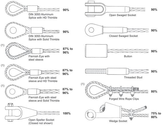
In above sketch, end connections marked (1) are used only with 6-strand wire ropes. Their efficiency rating depends on rope size and core type.
The swaging or clamping process compresses the rope to varying degrees causing a slight loss of rope strength.
Most of wire ropes have an actual breaking strength up to approximately 5%-15% higher than the breaking strength listed in catalogue. Due to this, wire ropes with even swaged fittings don’t fail at listed breaking strength and some manufacturers claim their assembly to have 100 % efficiency.
