Information about eye bolt’s material, specification, marking and application is given in this article.
Material, Specification and Marking
Eye bolts are made from forged carbon steel or alloy steel. Alloy steel eye bolts are forged, quenched, and tempered with improved toughness properties, intended primarily for low- temperature applications. Carbon steel eye bolts (ASTM A489) shall have the manufacturer’s name or identification mark forged in raised characters on the surface of the eye bolt. Alloy steel eye bolts (ASTM F541) shall have the symbol “A” (denoting alloy steel) and the manufacturer’s name or identification mark forged in raised characters on the surface of the eye bolt.
Eye bolts are made as per ANSI/ASME B18.15 and ASME B30.26.
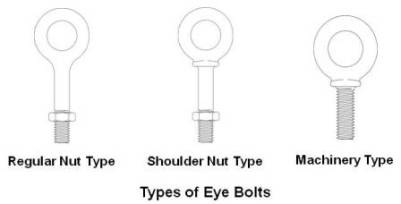
ASME B18.15 is limited to dimensions and capacities for forged threaded eye bolts intended primarily for lifting applications, and cover the following types and styles:
Type 1, Plain Pattern (straight shank); Style A – Long Length; Style B – Short Length.
Type 2, Shoulder Pattern; Style A – Long Length; Style B – Short Length.
Short Length Shoulder Pattern eye bolts are also known as Machinery Type eye bolts.
ASME B30.26 include identification, ductility, design factor, proof load and temperature requirements.
Eye bolts shall have a minimum design factor of 5, based on ultimate strength. Working Load Limit shown is for in-line pull.
Eye bolts manufactured in accordance with ASTM A489 (Standard Specifications for Carbon Steel Lifting Eyes) are rated for lifting service between +30°F and +275°F. These temperature limitations are also referenced in ASME B18.15 (Forged Eye bolts). Eye bolts manufactured in accordance with ASTM F 541 (Alloy Steel Eye bolts) are rated for use at a low temperature of -40°F. ASTM F 541 requires the symbol “A” to denote alloy steel.
Safe Working Load for Carbon Steel Shouldered Eye bolts as per ANSI/ASME B18.15 is as under.
| Norminal size (in.) | Inside diameter of eye (in.) | Safe Working Load for Shouldered Eye bolt (lb) | |||
|---|---|---|---|---|---|
| Vertical | 30° from vertical | 60° from vertical | 90° from vertical | ||
| 1/4 | 0.69 | 400 | 75 | Not recommended | Not recommended |
| 3/8 | 0.94 | 1,000 | 400 | 220 | 180 |
| 1/2 | 1.12 | 1,840 | 850 | 520 | 440 |
| 5/8 | 1.31 | 2,940 | 1,410 | 890 | 740 |
| 3/4 | 1.44 | 4,430 | 2,230 | 1,310 | 1,140 |
| 1 | 1.69 | 7,880 | 3,850 | 2,630 | 2,320 |
| 1 1/4 | 2.12 | 12,600 | 6,200 | 4,125 | 3,690 |
| 1 1/2 | 2.44 | 18,260 | 9,010 | 6,040 | 5,460 |
| 2 | 3.06 | 32,500 | 15,970 | 10,910 | 9,740 |
Safe Working Load for Carbon Steel Eye bolts as per ASME B30.26 for vertical (in-line) loading for Inch and Metric sizes are as under.
| Size (in.) | Working Load Limit (lbs.) |
|---|---|
| 1/4 | 650 |
| 5/16 | 1,200 |
| 3/8 | 1,550 |
| 1/2 | 2,600 |
| 5/8 | 5,200 |
| 3/4 | 7,200 |
| 7/8 | 10,600 |
| 1 | 13,300 |
| 1-1/4 | 21,000 |
| 1-1/2 | 24,000 |
| Metric Size | Working Load Limit – kg |
|---|---|
| m6 | 200 |
| m8 | 400 |
| m10 | 640 |
| m12 | 1000 |
| m16 | 1800 |
| m20 | 2500 |
| m24 | 4000 |
| m30 | 6000 |
| m36 | 8500 |
For angular lifts, adjust working load as follows:
| Direction of Pull | Adjusted Working Load |
|---|---|
| 45 degrees | 30% of rated working load |
| 90 degrees | 25% of rated working load |
IS 4190: 1984
Indian standard for eye bolts is IS 4190: 1984 (Specification for Eye Bolts with Collars). This standard specifies the basic dimensions, material, lifting capacity and conditions of use of lifting eyebolts of Grade M. These eyebolts, which are described as `universal` may be used in all cases involving vertical and inclined lifting. This standard covers only eyebolts with eyes of internal diameters capable of permitting direct engagement with eyehooks of the same lifting capacity (working load limit) for use with Grade T(8) chain. In the case of eyehooks for use with Grade M(4) chain, it may be necessary to use an intermediate component such as a shackle to make the connection.
Application
It is recommended to use shouldered eye bolts for rigging hardware, except when prohibited by the configuration of the item to which the eye bolt is attached. Where non-shouldered eye bolts are required, they shall be used only in vertical pulls or in rigging systems that are designed, analyzed, and approved by a qualified person.
For vertical loading, eye bolts without shoulders have the same load-carrying ability as shouldered eye bolts.
Shoulders of eye bolts shall seat uniformly and snugly against the surface on which they bear. Never undercut eye bolt to seat shoulder against the load. Always countersink receiving hole or use washers to seat shoulder.
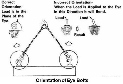
When more than one eye bolt is used in conjunction with multiple-leg rigging, spreader bars or lifting beams should be used to eliminate angular loading. In case two or more than two eye bolts are used without spreader bars, their orientation shall be such that load is in the plane of the eyes as shown below (Orientation of eye bolts). When eye bolts cannot be properly seated and aligned with each other, a steel washer or spacer not to exceed one thread pitch may be required to put below the eye bolt. Proper thread engagement must be maintained. Use a washer with approximately the same diameter as the eye bolt shoulder and the smallest inside diameter that will fit the eye bolt shank.
If the hook does not go completely into the eye bolt, use a shackle to avoid loading the hook tip.
Installation for In-line Loading
For in-line loading application use regular nut eye bolt or shoulder nut eye bolt. Use number of nuts based on thickness of load as shown below.
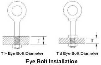
Use one nut if thickness is more than one eye bolt diameter. Use two nuts if thickness is less than or equal to eye bolt diameter. Always tighten nuts securely against the load.
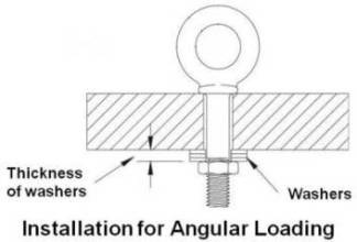
Installation for Angular Loading
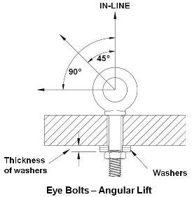
Use shoulder nut eye bolt for angular loading. If the eye bolt protrudes so far through the load that the nut cannot be tightened securely against the load, use properly sized washers to take up the excess space between the nut and the load as shown below. Thickness of washers / spacer must exceed the distance between the bottom of the load and the last thread of the eye bolt.
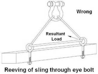
Reeving of Sling
Slings shall not be reeved through an eye bolt or reeved through a pair of eye bolts. Reeving will alter the angle of loading on the eye bolt as shown below. Only one leg should be attached to each eye bolt.
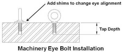
Machinery Eye Bolt – Installation for In-line & Angular Loading
These eye bolts are primarily intended to be installed into tapped holes. For installation, tap the load (tap depth) to a minimum depth of one-half the eye bolt size beyond the shank length of the machinery eye bolt. If the plane of the machinery eye bolt is not aligned with the sling line, add shims (washers) of proper thickness to adjust the angle of the plane of the eye to match the sling line as shown below.
To attain the rated capacity, minimum thread shank length of engagement depends on parent material and must be as follows:
Steel: 1 thread diameter
Cast iron, brass, bronze: 1.5 times the thread diameter
Aluminum, magnesium, zinc, plastic: 2 times the thread diameter
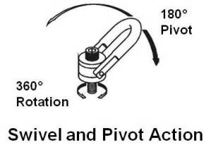
Swivel Hoist Ring
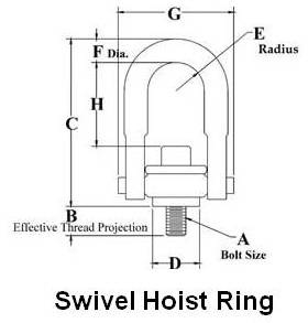
Swivel hoist ring shown above is a patented product manufactured by The Crosbygroup Inc. and is available in UNC and Metric thread sizes. One of the main advantages for its use is self alignment of its eye with the load angle due to swivel movement and they are rated 100% for 90 degree angle. It gives 360° swivel and 180° pivot action as shown below.
Eye Bolt Inspection
Visually inspect each eye bolt before use. Eye bolts that are worn, cracked, bent, elongated or have damaged threads shall be discarded. Ensure that threads on shank and receiving hole are clean.
Note:
For more information on eye bolts (dimensions) and swivel hoist rings (different type of rings) please refer General Catalog of the Crosby Group.
Acknowledgement:
Sketches in this article are based on sketches in General Catalogue by Crosby Group.
