Wire rope clips serve as an alternative to splicing and are a simple mechanical means of securing a wire rope round a thimble. They are also known as Bulldog Clips or wire rope clamps. Information about specification and method of installing wire rope clips is given in this article.
Wire rope clips are made from two types of materials. They are malleable iron and drop forged steel. Malleable wire rope clips are to be used only for non-critical, light duty applications with small applied loads. They should not be used for lifting or suspending load.
Specifications
Wire rope clips are made as per Federal Specification FF-C-450D and ASME B30.26.
As per Federal Specification, they are classified as under.
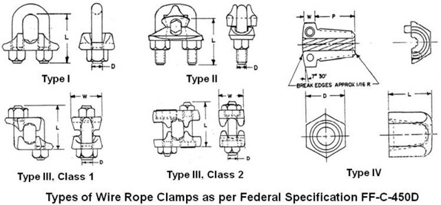
Type I: Single grip, single saddle, with U-bolts and nuts. They are made in two classes.
Class 1 – Steel saddle.
Class 2 – Malleable iron saddle.
Type II: Double grip, double saddle, with U-bolt and nuts.
Type III: Double grip, double saddle, with bolt and nuts. They are made in two classes.
Class 1: Assembled with integral L-shaped bolts and nuts.
Class 2: Assembled with separate hex head bolts and nuts.
Type IV: Double grip, two taper threaded half clamps with hexagon nut.
Type I and Type III clips are widely used in the industry.
Type III clips having double saddle design eliminates the possibility of incorrect installation.
For dimensional detail, please refer the specification or Crosby’s General Catalog.
For elevator, personnel hoist, and scaffold applications, refer ANSI A17.1 and ANSI A10.4. These standards do not recommend U-Bolt style wire rope clip terminations.
For OSHA (Construction) applications, see OSHA 1926.251.
Tables showing minimum number of clips to be installed, amount of wire rope required to turn back and tightening torque for various sizes of forged wire rope clips meeting performance requirements of Federal Specification FF-C-450D, Type I, Class 1 and Type III are given below.
Type I, Class 1 Clips
| Clip Size (in.) | Rope Size(mm) | Minimum No. of Clips | Amount of Rope to Turn Back in mm | *Torque in Nm. |
|---|---|---|---|---|
| 1/8 | 3-4 | 2 | 85 | 6.1 |
| 3/16 | 5 | 2 | 95 | 10.2 |
| 1/4 | 6-7 | 2 | 120 | 20.3 |
| 5/16 | 8 | 2 | 133 | 40.7 |
| 3/8 | 9-10 | 2 | 165 | 61.0 |
| 7/16 | 11-12 | 2 | 178 | 88 |
| 1/2 | 13 | 3 | 292 | 88 |
| 9/16 | 14-15 | 3 | 305 | 129 |
| 5/8 | 16 | 3 | 305 | 129 |
| 3/4 | 18-20 | 4 | 460 | 176 |
| 7/8 | 22 | 4 | 480 | 305 |
| 1 | 24-25 | 5 | 660 | 305 |
| 1-1/8 | 28-30 | 6 | 860 | 305 |
| 1-1/4 | 33-34 | 7 | 1120 | 488 |
| 1-3/8 | 36 | 7 | 1120 | 488 |
| 1-1/2 | 38-40 | 8 | 1370 | 488 |
| 1-5/8 | 41-42 | 8 | 1470 | 583 |
| 1-3/4 | 44-46 | 8 | 1550 | 800 |
| 2 | 48-52 | 8 | 1800 | 1017 |
| 2-1/4 | 56-58 | 8 | 1850 | 1017 |
| 2-1/2 | 62-65 | 9 | 2130 | 1017 |
| 2-3/4 | 68-72 | 10 | 2540 | 1017 |
| 3 | 75-78 | 10 | 2690 | 1627 |
| 3-1/2 | 85-90 | 12 | 3780 | 1627 |
Type III Clips
| Clip Size (in.) | Rope Size(mm) | Minimum No. of Clips | Amount of Rope to Turn Back in mm | *Torque in Nm. |
|---|---|---|---|---|
| 3/16 | 5 | 2 | 100 | 40.7 |
| 1/4 | 6-7 | 2 | 100 | 40.7 |
| 5/16 | 8 | 2 | 127 | 40.7 |
| 3/8 | 9-10 | 2 | 133 | 61.0 |
| 7/16 | 11-12 | 2 | 165 | 88.1 |
| 1/2 | 13 | 3 | 279 | 88.1 |
| 9/16 | 14-15 | 3 | 323 | 176 |
| 5/8 | 16 | 3 | 342 | 176 |
| 3/4 | 18-20 | 3 | 406 | 305 |
| 7/8 | 22 | 4 | 660 | 305 |
| 1 | 24-25 | 5 | 940 | 305 |
| 1-1/8 | 28-30 | 5 | 1040 | 488 |
| 1-1/4 | 32-34 | 6 | 1400 | 488 |
| 1-3/8 | 36 | 6 | 1570 | 678 |
| 1-1/2 | 38-40 | 7 | 1980 | 678 |
*The tightening torque values shown are based upon the threads being clean, dry, and free of lubrication.
Note: Above tables are reproduces from Crosby’s General Catalog.
Method of Installing Wire Rope Clips
When using wire rope clips, extreme care must be exercised to make certain that they are attached correctly. Failure to do so could result in serious injury or death. Carry out their installation as under.
Match the same size wire rope clip to the same size rope diameter. For example, use a 3/8” wire rope clip with a 3/8” wire rope. Inspect wire rope clip nuts before and after each use.
Wire rope clips should be placed on the wire rope connection with the corrugation in their saddles coinciding with the lay of the wire rope. Generally saddles are provided with right-hand helix. For wire rope with left-hand helix, use clips having left-hand helix.
Making an Eye with a Thimble
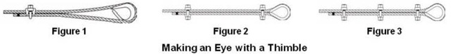
Turn back specified length of wire rope from thimble (please refer tables given above). Put first clip one saddle width from seized “dead end” (Figure 1). Seat “live end” (load carrying part) of wire rope in saddle and position U-bolt over “dead end.” Tighten nuts evenly to proper torque.
Put the second clip as near the loop or thimble as possible (Figure 2). Install nuts firmly but do not yet tighten to proper torque.
Install all remaining clips equally spaced between the first two clips (Figure 3). Install nuts firmly but do not yet tighten to proper torque.
Apply light tension to wire rope assembly to take up rope slack and then tighten all nuts evenly to proper torque.
Add at least one more clip if a pulley (sheave) is used in place of a thimble. If more clips are used than specified, proportionally increase the amount of wire rope that is turned back.
If Seale construction or similar large outer wire type construction in the 6 x 19 Class is to be used for sizes 1 inch and larger, add one additional clip.
After assembly, first apply load to test the assembly. This load should be of equal or greater weight than loads expected in use. Next, check and retighten nuts to recommended torque.
When the required minimum number of clips are installed and nuts are tightened to required torque, the assembly will develop up to 80% efficiency for clip sizes 1/8" through 7/8" and 90 % for sizes 1" through 3-1/2"
If more number of clips are used than shown in the table, the amount of turnback should be increased proportionately.
Wire Rope Splicing (joining) Procedures
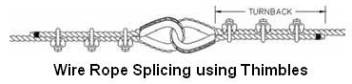
The preferred method of splicing two wire ropes together is to use inter-locking turnback eyes with thimbles, using the recommended number of clips on each eye as shown above.
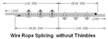
An alternate method (without using thimbles) is to use twice the number of clips as used for a turnback termination as shown below. In this method the rope ends are placed parallel to each other, overlapping by twice the turnback amount. The minimum number of clips should be installed on each dead end. All other instructions given above shall be followed.
In accordance with good rigging and maintenance practices, the wire rope end termination should be inspected periodically for wear, abuse, and general adequacy.
