Microstructures have a strong influence on the properties and successful application of metals and alloys. Hence the primary objective of metallographic study is to find out the constituents and structure of a metal or an alloy. Many specifications contain a requirement regarding microstructure; hence metallographic examination is inspection to ensure that the requirement is met. It is also useful in failure analysis and in research and development. Information on preparation of a specimen, microscope and In-situ Metallography is given in this article.
Microstructure and Macrostructure
The structure of polished and etched metals as revealed by a microscope at a magnification greater than ten diameters is called microstructure. By microscopic study, it is possible to determine grain size and the size, shape, and distribution of various phases and inclusions which have a great effect on the mechanical properties of the metal. The microstructure will also reveal the mechanical and thermal treatment on the metal.
The structure of metals as revealed by examination of the etched surface of polished specimen at a magnification not exceeding ten diameters is called macrostructure. It is used for the investigation of defects and structure of a large area as opposed to a microscopic portion of that area. This study is carried out to reveal solidification of structure, flow lines, segregation, structural changes due to welding, general distribution and size of inclusions, porosity, ingot defects and fabricating defects.
Preparation of a Specimen
Specimen preparation (known as polishing) is necessary to study its microstructure as metallurgical microscope makes use of the principle of reflection of light to obtain image of the metal structure.
Satisfactory image of the micro structure can be obtained only when the specimen has been carefully prepared. Even the most expensive microscope will not reveal the metal structure if the specimen has been poorly prepared. The procedure to be followed in the preparation of a specimen is simple but the technique gets developed only after practice. The final objective is to produce a flat, scratch-free and mirror like surface. The procedure for preparing the specimen for both macro and micro examination is the same except that in the later case the final surface finish is more important than in the former. The steps required to prepare a metallographic specimen are as under.
Selection of specimen
Specimen should be selected from that area of material (plate, casting, etc.) which can be taken as representative of the material that is being studied.
For general study, specimens should be chosen from locations most likely to reveal the maximum variations within the material under study. For example, in case of castings specimens could be selected from the zones within which maximum/minimum segregation might be expected.
In case of study of failures, specimen should be taken as close as possible to the fracture or to the initiation of the failure.
In many cases, specimens are required to be taken from a sound area for a comparison of structure and properties.
After deciding the location of the specimen, the type of section to be examined must be decided.
For a casting, a section cut perpendicular to the surface will show the variation in structure from outside to interior of the casting. Transverse sections or cross sections taken perpendicular to the main axis of the material are useful for study of decarburization at the surface of a ferrous material, depth of corrosion, thickness of protective coating etc. Longitudinal sections taken parallel to the main axis of the material is useful in study of plastic deformation as shown by grain distortion.
The location of surface examined should always be given in reporting results.
Size of Specimen
For convenience, specimens to be polished are generally not more than about 12 to 25 mm square or approximately 12 to 25 mm in diameter.
Cutting of the specimen
After selecting a particular area, the specimen may be removed from the material by sawing or cutting using abrasive wheel. The specimen shall be kept cool during the cutting operation. While cutting, care must be taken to minimize altering the structure of the metal. A material in the form of wire, rod, sheet or plate may be cut by a shear, a type of cutting tool having two opposing blades.
All cutting operation produces some depth of damage, which will have to be removed in subsequent preparation steps.
Rough Grinding
After cutting, a soft specimen may be made flat by slowly moving it up and back across the surface of a smooth file. Soft or hard specimen may be rough ground on a belt, disc or surface sander. Grinding is accomplished by abrading the specimen surface through a sequence of operation using progressively finer abrasive grit. Grit size from 40 mesh through 150 mesh are usually regarded as coarse abrasive (for rough grinding), and grit sizes from 180 mesh through 600 mesh as fine abrasives (for fine grinding). Grinding abrasives commonly used are silicon carbide (SiC), aluminium oxide (Al2O3), emery (Al2O3 – Fe3O4) and diamond particles. An abrasive grit size 150 or 180 mesh is coarse enough to use on specimen surfaces cut by an abrasive cutoff wheel. Hacksawed surface require grit size in the range of 80 to 150. To ensure the complete elimination of the previous grinding scratches found by visual inspection, the direction of grinding must be changed 45° to 90° between successive grit sizes. Rough grinding is continued until all scratches due to the hacksaw or cutoff wheel are no longer visible and the surface is flat.
Specimens such as fractures or those where it is necessary to examine the edges are often plated to obtain good edge retention prior to their mounting. Plating can be done electrolytically or with electroless solutions.
Mounting of specimen
Mounting of a specimen is carried out for convenience in handling it during the subsequent steps of metallographic preparation and examination. For this, the specimen is either clamped or mounted. Compression mounting involves molding around the specimen by molding materials like Bakelite, Lucite and acrylic resins by application of heat and pressure. Epoxy or polyester resins are used for cold molding.
Fine Grinding
After mounting, the specimen is finely ground using successively fine abrasives (grit sizes from 180 mesh through 600 mesh).
Abrasive grit size designations in this article are as per the ANSI (American National Standards Institute) or CAMI (Coated Abrasive Manufacturers Institute) system units. To visualize their actual size, their size in microns (µm) is given in the table given below. For ready reference/comparison, Grit Numbers as per FEPA (European Federation of Abrasive Producers) and their size are also included in the table.
| ANSI / CAMI | FEPA | ||
|---|---|---|---|
| Grit Number | Size in Microns (µm) | Grit Number | Size in Microns (µm) |
| 120 | 116.0 | P120 | 125.0 |
| 180 | 78.0 | P150 | 100.0 |
| 240 | 51.8 | P280 | 52.2 |
| 600 | 14.5 | P1200 | 15.3 |
| 800 | 11.5 | P1500 | 12.6 |
| 1500 | 8.0 | P2500 | 8.4 |
Polishing
Compared to grinding which is carried out on a belt, disc or surface sander, polishing is usually carried out by the use of loose abrasive (≤6µm) embedded in an appropriately lubricated supporting surface.
The time consumed and the success of polishing depends largely upon the care that was exercised during fine grinding. The final approximately flat scratch free surface is obtained by use of a wet rotating wheel covered with special cloth charged with abrasive particles. During polishing, the specimen is rotated in a direction counter to the rotation of the polishing wheel. In addition, the specimen is continually moved back and forth between the center and edge of the wheel, thereby ensuring even distribution of the abrasive and uniform wear of the polishing cloth. The correct amount of applied pressure must be determined by experience. In general, firm hand pressure is applied to the specimen in the initial polishing step and is proportionally decreased with successively finer polishing steps. A wide range of abrasives is available for polishing. Generally alpha grade of aluminium oxide (in a range of particle sizes from 15 micron to 0.3 micron) is used for rough polishing and gamma grade of aluminium oxide (0.05 micron particle size) is used for fine polishing of ferrous and copper based materials and cerium oxide for aluminium, magnesium and their alloys. Other polishing abrasives often used are chromium oxide, magnesium oxide and diamond paste (6 micron diamond for rough polishing and 1 micron diamond for fine polishing).
After polishing, the specimen is washed in warm running water, rinsed with methanol or any other alcohol that does not leave a residue, and dried in a stream of warm air.
Etching
The purpose of etching is to make visible structural characteristics of the metal or alloy. The process shall be such that the various parts of the microstructure can be clearly differentiated. This is achieved by use of an appropriate reagent which carries out chemical action to polished surface. In alloys composed of two or more phases, the phases are revealed due to preferential attack by the reagent to them due to difference in their chemical composition. In the same way grain boundaries are visible as they are attacked at different rate than grain surfaces.
Etching is done by immersing the polished surface in the reagent or by rubbing the polished surface gently with a cotton swab wetted with the etching reagent. After etching, the specimen is again washed thoroughly and dried. Now the specimen can be studied under a microscope.
The selection of the appropriate etching reagent is determined by the metal or alloy and the specific structure desired for viewing. Common etching reagents used for various metals and alloys are as under.
| Etching Reagent | Composition | Use |
|---|---|---|
| Nitric acid (natal) |
White nitric acid – 1 to 5 ml Ethyl or methyl alcohol – 100 ml (95% or absolute) (also amyl alcohol) | Carbon steels – to get better contrast |
| Picric acid (picral) |
Picric acid – 4 g Ethyl or methyl alcohol – 100 ml (95% or absolute) | Carbon steels |
| Ferric chloride and hydrochloric acid | Ferric chloride – 5 g Hydrochloric acid – 50 ml Water – 100 ml | Structure of austenitic nickel and stainless steel |
| Ammonium hydroxide and hydrogen peroxide | Ammonium hydroxide – 5 parts Water – 5 parts Hydrogen peroxide – 2 to 5 parts | Copper and its alloys |
| Ammonium persulfate | Ammonium persulfate – 10 g Water – 90 ml | Copper, brass, bronze, aluminium bronze, silver, nickel |
| Palmerton reagent | Chromic oxide – 200 g Sodium sulfate – 15 g Water – 1000 ml | Zinc and its alloys |
| Ammonium molybdate | Molybdic acid (85%) – 100g Ammonium hydroxide (sp. gr. 0.9) – 140 ml Water – 240 ml Filter and add to nitric acid (sp. gr. 1.32) – 60 ml | Lead and its alloys |
| Hydrofluoric acid | Hydrofluoric acid (concentrated) – 0.5 ml Water – 99.5 ml |
Aluminium and its alloys |
Metallurgical Microscopes
In comparison with a biological type, the metallurgical microscope differs in the manner by which the specimen is illuminated. Since a metallographic sample is opaque to light, the sample must be illuminated by reflected light. A simplified ray diagram of a metallurgical microscope is shown below.
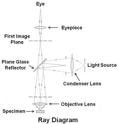
The prepared specimen is placed perpendicular to the optical axis of the microscope and is illuminated through the objective lens by light from the source, which is focused by the condenser into a beam that is made approximately parallel to the optical axis of the microscope by the plane glass reflector. The light is then reflected from the surface of the specimen. This light reflected from the specimen surface will be magnified in passing through the objective lens and will continue upward through the plane glass reflector and gets magnified again by the eyepiece.
The direction of light reflected from specimen depends on specimen’s surface condition (surface of grain, grain boundary, etc.) as shown below.
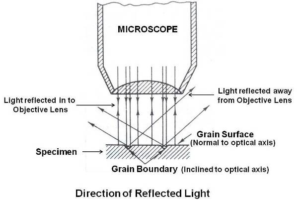
The light is reflected from the surface of the specimen in to objective lens from features approximately normal to the optical axis and away from objective lens from features inclined to the optical axis. The final image of the specimen, which is formed by the eyepiece, is therefore bright for all features normal to the optical axis (grain) and dark for inclined features (grain boundary). In this way, the various micro-structural features of a metallographic specimen such as grain boundaries that have been etched to produce grooves with inclined edges, precipitate particles and inclusions that have either been etched or polished in such a way that their edges are inclined are revealed.
It is possible to mount a camera above the eyepiece and use the microscope for photomicrography. The maximum magnification obtained with optical microscope is about 2000x. The limitation is due to the wavelength of visible light which limits the resolution of fine detail in the metallographic specimen.
For higher resolutions, electron microscopes are used. In principle the electron microscope is similar to the light microscope. In electron microscope, light rays are replaced by a beam of electrons. An electron microscope has a basic magnification range of 1400 to 32000x, which may be extended to 200000x with accessory lenses. Since metallographic specimens are opaque to an electron beam, it is necessary to prepare, by special technique, a thin replica of surface to be studied. For this, the specimen is polished and etched following normal metallographic practice. It is then placed on a hot plate with a small pellet of suitable plastic on the etched surface. As the temperature rises, the plastic softens and pressure is applied on it to ensure intimate contact between the plastic and the surface. After cooling, the replica is carefully peeled off. To improve contrast, a thin coating of carbon or tungsten is evaporated onto the replica at an angle from one side. Since the thin replica is fragile, it is supported on a disk.
In-situ Metallography
In-situ Metallography is an NDE (non destructive examination) technique. In-situ Metallography and replication is used for microstructural analysis for examining large components that cannot be easily moved or destructive sample preparation is difficult or not permissible. It is ideal for assessing the remaining life of power and petrochemical plants.
For in-situ metallography, a location on the component is carefully chosen. This location (area) is polished using portable grinding machine and then etched in a suitable medium. Portable microscopy is then performed to ensure that a good clean etch has been established. The microstructure is replicated using cellulose acetate replicating tape and methyl acetate solvent. A drop of solvent is placed on the prepared surface and the replicating tape is pressed into the solvent. After ten minutes, the solvent evaporates and the plastic tape is peeled from the surface. A three dimensional, reverse image of the surface is preserved on the replica. Microstructural detail as fine as 0.1 micron can be accurately replicated by this method. The acetate tape after removal is secured to a glass microscope slide.
Observations can be made both in the field as well as at the laboratory. For field use, a portable microscope (400X magnification) is used to observe prepared metal surfaces and the quality of the replica. In the laboratory, detailed microscopic examinations are made, including digital photographs to document the microstructures collected in-situ.
Generally the guidelines given in ASTM E1351 (Standard Practice for Production and Evaluation of Field Metallographic Replicas) is followed for In-situ Metallography.
For more information on metallography, please refer following ASTM standards.
E7 – Standard Terminology Relating to Metallography
E3 – Standard Guide for Preparation of Metallographic Specimens
E340 – Standard Test Method for Macroetching Metals and Alloys
E407 – Standard Practice for Microetching Metals and Alloys
Note:
Since Metallography is more of an art then technique, the service shall be out sourced from a reputed laboratory.
