Next to the hardness test, the tensile test is most frequently performed to determine mechanical properties. Information on various tensile properties like proportional limit, elastic limit, yield point, yield strength, ultimate strength, breaking strength, proof stress, percent elongation, percent reduction in area and modulus of elasticity is given in this article.
Tensile Test
In tensile testing, material to be tested is machined to standard dimensions. Generally 12.5 mm round test specimen as shown below is used for the test.
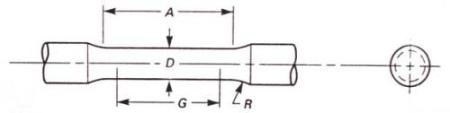
Where,
G - Gauge length = 50.0 mm
D - Diameter = 12.5 mm
R - Radius of fillet = 10 mm and
A = Length of reduced section = 60 mm.
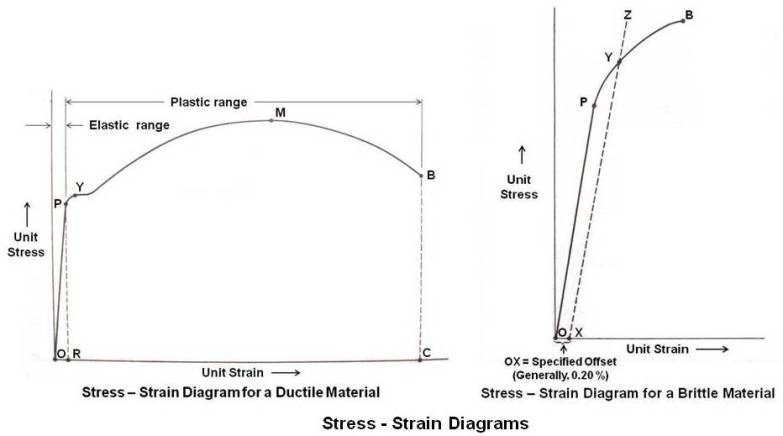
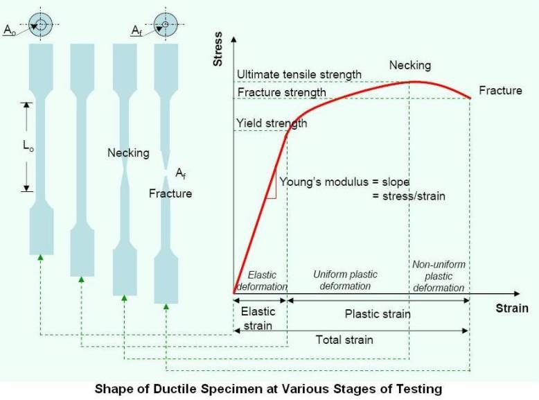
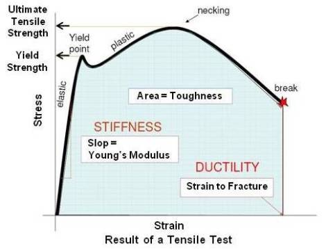
The specimen is gauge marked with a center punch, scribe marks or drawn with ink. The purpose of these gage marks is to determine the elongation. The elongation is measured by an arrangement consisting of dial gauge and clamps called the extensometer. The testing machine (Universal Testing Machine) is equipped with a loading system of mechanical (screw power) or hydraulic type. The specimen is fitted in the jaws of the testing machine and subjected to a tensile load. The applied load (stress) and the resulting elongation (strain) of the specimen are measured. The process is repeated with increased load until the specimen breaks. Using these readings a stress - strain diagram is plotted to find out tensile properties. The unit stress (intensity of stress) is the load per unit area of the cross section of the specimen and is plotted as the ordinate in stress - strain diagram. The unit strain (unit deformation) at any stress is the extension of the gauge length undergone by the specimen per unit length (measured elongation divided by gauge length) under that stress. Unit strain is plotted as the abscissa in stress - strain diagram. The relation between unit stress and unit strain found experimentally is represented by the stress - strain diagram. It may be noted that stress-strain diagrams are typically based upon the original cross sectional area and the initial gage length, even though these quantities change continuously during the test. These changes have a negligible effect except during the final stages of the test. The stress - strain diagrams for a ductile and a brittle material are shown below. The test is carried out at room temperature. Testing temperature affects mechanical properties. Information on it is given in article on impact test (next article). Shape of the ductile material specimen during various stages of the test is also shown schematically.
Tensile Properties
The properties which may be determined by a tensile test (with reference to stress - strain diagrams for a ductile and a brittle material shown above) are as under.
Proportional Limit and Modulus of Elasticity
It is found that the initial portion of the stress - strain diagram is a straight line OP for most materials used in engineering structures/components. In this range, the stress (σ) and strain (ε) are proportional to each other. Therefore we can write, σ=Exε. This relationship is known as Hooke's Law.
E, the slope of the straight line portion of the stress - strain diagram is called the Modulus of Elasticity or Young's Modulus.
Proportional limit is the maximum stress under which a material will maintain a perfectly uniform rate of strain to stress. Thus the stress at the limit of proportionality point P is known as the proportional limit.
If within this stress, the load on the test specimen is removed at any time, the extensometer needle will return to zero (initial position). This indicates that the strain, caused by the load, is elastic.
Elastic Limit
If the load is increased after proportionality point P, then released after each increment and the extensometer checked, a point will be reached at which the extensometer needle will not return to zero. This indicates that the material now has permanent deformation. The elastic limit may therefore be defined as the minimum stress at which permanent deformation first occurs. Most materials can be stressed slightly above the proportional limit without taking a permanent set. It may be noted that now the curve is not straight line.
For most materials the elastic limit has nearly the same numerical value as the proportional limit.
Yield Point
As the load in the specimen is increased beyond the elastic limit, a stress is reached at which the material continues to deform without an increase of load. The stress at point Y in stress - strain diagram for a ductile material is known as Yield Point. This phenomenon occurs only in certain ductile materials.
Since yield point is relatively easy to determine and the permanent deformation is small up to yield point, it is very important value in design of machine members.
It may be noted that plastic deformation takes place in the specimen after elastic limit is reached. This deformation is of a permanent type, that is, the deformation remains even after load is removed.
Yield Strength
As can be seen in the stress - strain diagram for brittle materials, most nonferrous materials and the high strength steels do not show a well defined yield point (there is a smooth transition from elastic to plastic region – no distinct yield point). For these materials, the maximum useful strength is the yield strength.
Yield strength is the stress at which a material exhibits a specified limiting deviation from the proportionality of stress to strain. This value is usually determined by the offset method. As shown in stress - strain diagram for brittle a material, the specified offset OX is laid off along the strain axis. Then XZ is drawn parallel to OP, and thus Y, the intersection of XZ with the stress - strain diagram, is located. The value of the stress at point Y gives the yield strength. The value of offset is generally 0.20 percent of the gauge length.
In recording values of yield strength by this method, the specified value of offset used shall be stated in parentheses after the term yield strength, thus:
Yield strength (0.2 % offset) = 52000 psi (360 MPa)
Ultimate Strength
As the load on the specimen is increased still further, the stress and strain increases, as shown by the portion of curve YM for a ductile material, until the maximum stress is reached at point M. The ultimate strength or the tensile strength is therefore the maximum stress developed by the material based on the original cross sectional area. On loading further, a ductile material will continue to stretch and will fracture at point B. In case of a brittle material, it breaks when stressed to the ultimate strength at point B as shown in stress - strain diagram for a brittle material.
Ultimate tensile strength is the value most frequently used from tensile test results. It is used for specification and quality control. However, in engineering design, safety factor shall be applied.
Breaking Strength
For a ductile material up to the ultimate strength, the deformation is uniform along the length of the bar. At the maximum stress (ultimate strength), localized deformation or necking occurs in the specimen, and the load falls off as the area decreases. This necking elongation is a nonuniform deformation and occurs rapidly to the point of failure. The breaking strength (point B in stress - strain diagram for a ductile material), which is determined by dividing the breaking load by the original cross sectional area, is always less than the ultimate strength. For brittle material, the ultimate strength and breaking strength coincide.
Ductility
The ductility of a material is indicated by the amount of deformation that is possible until fracture. This is determined in a tension test by two measurements.
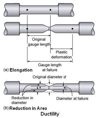
Percent Elongation
This is determined by fitting together, after fracture, the parts of the specimen and measuring the distance between the original gauge marks.

Where,
Lf = final gauge length and
Lo = original gauge length, usually 2 inch.
In reporting percent elongation, the original gauge length must be specified since the percent elongation will very with gauge length.
Reduction in Area
This is also determined from the broken halves of the tensile specimen by measuring the minimum cross sectional area and using the following formula.
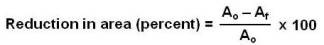
Where,
Ao = original cross sectional area and
Af = final cross sectional area
An overly simplistic way of viewing ductility is the degree to which a material is "forgiving" of local deformation without the occurrence of fracture.
In general a material is considered to be brittle if percent elongation is ≤ 5 at fracture and ductile if percent elongation and reduction in area (both) are ≥ 25.
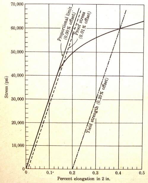
Proof Stress
Since it is difficult to measure elastic limit, a newer method - that of proof stress has been developed. Proof stress is the maximum stress a material can withstand without taking more than a small amount of set. The amount is usually specified as the smallest that can be measured by the extensometer, namely, 0.01 percent in 2 inch. As with the yield strength, the preferred method of measuring proof stress is by using a 0.01 percent offset. This is shown in the figure given below (the proportional limit and yield strength are also shown to explain the term clearly).
True Stress Strain Diagram
It might be expected that after the elastic limit is reached the specimen might begin to yield and finally fracture without further increase of stress but the stress - strain diagrams show that the stress continues to increase even after elastic limit has been passed. This fact is due to the strain hardening of the material due to cold working. The more the specimen is deformed, the harder and stronger it becomes because of increased resistance to slip (more detail about this is given in an article titled plastic deformation).
In case of ductile materials, the specimen uniformly increases in strength and at the same time decreases uniformly in cross section until point M (ultimate strength) is reached. Here, the rate of reduction in area exceeds the rate of work hardening, and the strain becomes so great that the contraction of area begins to be localized at some point in the specimen which begins to neck down. The reduction in cross sectional area takes place so rapidly that the stress actually drops as shown by MB portion of the graph on the diagram for a ductile material and fracture takes place at point B.
In case of brittle materials, the specimen uniformly increases in strength and at the same time decreases uniformly in cross section until ultimate strength (point B) is reached and fracture takes place.
Thus, conventional tensile test gives valuable information up to the point of yielding. Beyond this point, the stress values are fictitious since the actual cross sectional area will be considerably reduced. The true stress is determined by the load divided by the cross sectional area at that moment of loading. The true strain is determined by the change in length divided by the immediately preceding length.

The true stress - strain diagram shown above gives useful information regarding plastic flow and fracture of metals.
For more information on tensile test, please refer following three ASTM standards.
A370 – Test Methods and Definitions for Mechanical Testing of Steel Products
E6 – Terminology Relating to Methods of Mechanical Testing
E8 – Test Methods for Tension Testing of Metallic Materials
Important Properties of a Material
Important Properties of a Material are listed in the table given below.
| Property | Meaning |
|---|---|
| Hardness | Resists penetration by a sharp object |
| Toughness | Resists failure by impact / energy to fracture |
| Ductile | Deforms without breaking |
| Brittle | Fails at maximum load, in contrast to ductile |
| Stiff | Resistance of an elastic body to deformation |
| Strong | Requires large force before rupture/deformation |
| Thermal shock resistant | Resists fracture from changes or gradients in temperature |
Difference between strong and stiff
In materials science, the strength of a material is its ability to withstand an applied stress without failure. Yield strength refers to the point on the engineering stress-strain curve (as opposed to true stress-strain curve) beyond which the material begins deformation that cannot be reversed upon removal of the loading. Thus strength is related to plastic deformation.
Stiffness is the resistance of an elastic body to deformation by an applied force (tensile, shear, torsional, etc.). For the axial tension or compression, Young's modulus is the measure of the stiffness of a material. The stiffness of a structure is of principal importance in many engineering applications, so the modulus of elasticity is often one of the primary properties considered when selecting a material. A high modulus of elasticity is sought when deflection is undesirable, while a low modulus of elasticity is required when flexibility is needed.
Difference between ductility and malleability
Ductility and malleability are the property of a material to undergo permanent change in their shape without fracture at room temperature. However the difference between them is as under.
Ductility is the ability of a material to deform plastically without fracturing, being measured by elongation or reduction of area in a tensile test. This is often characterized by the material's ability to be stretched into a wire.
Malleability is the characteristic of metals which permits plastic deformation in compression without rupture. This is often characterized by the material's ability to form a thin sheet by hammering or rolling.
Ductility and malleability do not always correlate with each other; for instance, gold is both ductile and malleable, but lead is only malleable. Commonly, the term "ductility" is used to refer to both concepts, as they are very similar.
Ductility and malleability are important in metalworking, as materials that crack or break under stress cannot be manipulated using metal forming processes, such as hammering, rolling and drawing. Malleable materials can be formed using stamping or pressing, whereas brittle metals (for example cast irons) must be molded.
Toughness
Information about toughness is covered in the next article on impact test.
