Fatigue is the mechanism whereby cracks grow in a component/structure. Growth only occurs under fluctuating stress. Final failure generally occurs in regions of tensile stress when the reduced cross-section becomes insufficient to carry the peak load without rupture. Many structures, such as building frames, do not experience sufficient fluctuating stress to give rise to fatigue problems. However fatigue is very important in design of bridges, offshore structures, cranes, etc. which are subjected to fluctuating load which is a higher proportion of the total load. The fatigue test is a dynamic type of test which determines the relative behavior of materials when subjected to repeated or fluctuating loads. It attempts to simulate stress conditions developed in machine parts by cycling loads in real life loading/stress conditions.
The creep test determines the continuing change in the deformation of a material at elevated temperature when stressed below the yield strength.
Thermal fatigue and creep are the two damage mechanisms of principal concern for high-temperature, high-pressure steam plant equipment. Information about fatigue, fatigue test, fatigue fracture, creep and creep test is given in this article.
Note:
You may read this article after reading articles on plastic deformation and stress concentration. You may find difficulty in understanding this article if you do not know about them. This article is placed here to group all type of tests together.
Fatigue
Simply stated, fatigue is a form of failure that occurs in materials subjected to fluctuating stresses. Under fluctuating stresses, it is possible for failure to occur at a stress level considerably lower than the tensile or yield strength for a static load. Fatigue depends on the frequency and magnitude of the stress cycles.
Failure of a material due to fatigue may be viewed on a microscopic level in three steps as under.
Crack Initiation:
The initial crack occurs in this stage. The crack may be caused by surface scratches caused by handling, or tooling of the material, slip bands or dislocations. Dislocations play a major role in the fatigue crack initiation. In the first stage, dislocations accumulate near surface stress concentrations. After a large number of loading cycles, this leads to tiny steps in the surface that serve as stress risers where tiny cracks (called microcracks) can initiate. With passage of time, these microcracks join together and begin to propagate through the material in a direction that is perpendicular to the maximum tensile stress. Eventually, the growth of one or a few crack of the larger cracks will dominate over the rest of the cracks.
Crack Propagation:
The crack continues to grow during this stage as a result of continuously applied stresses.
Failure:
Failure occurs when the material that has not been affected by the crack cannot withstand the applied stress (overload). This stage happens very quickly.
In fatigue, the cyclic or fluctuating stresses are caused by mechanical loads, vibration (for example, flow-induced), or thermal ratcheting. Thermal fatigue is the result of cyclic stresses caused by temperature gradients that vary with time, e.g., startup and shutdown and to a lesser degree, a step change in load. In large or thick-walled equipment components, thermal stresses are caused by differences between surface and interior temperatures which occur when the surface temperature is allowed to change rapidly with changes in operating mode.
Thus fatigue is the initiation and stable propagation of a crack. A fracture occurs when a critical crack size is reached. The fatigue normally occurs at the high local stress and stress concentration areas such as header ligaments, welded joints (due to non-fusion flaws, incomplete penetration, undercuts, etc.) or mechanical discontinuities (machining undercuts, cracks, etc.).
Since scratches and other imperfections on the surface initiate crack, leading to decrease in the life of a material (due to fatigue), hard chrome platting is carried out on components of critical high speed equipments like shaft of boiler feed pump. During maintenance, such components shall be handled very carefully so that it does not result in scratches / damage on their surface. In case any sharp scratch is found, it shall be rounded by filing.
Fatigue cracking, a localized phenomenon, can be detected by conventional NDE (non destructive examination) methods and repaired by welding.
Fatigue Test
In tests like hardness test and tensile test, they indicate how metals behave when they are stressed only once. But, in service, metals have to be subjected to thousands, or even millions of stress reversals. The tensile test commonly employed for the determination of the strength of metals does not furnish any idea of the capacity of the metal to stand up to such repetitions of alternating stresses. The failure of a material under repeatedly applied stress is known as due to fatigue and in order to determine the capacity of a material to withstand such repetitions of stress, test known as fatigue test is performed.
Fatigue test is carried out on a fatigue testing machine. The machine has a mechanism to change magnitude of stress applied on the specimen. The type of stress (tension, compression, bending, torsion, etc.) which can be tested depends on the design of the machine. During testing, the stress applied on the specimen continually alternates between two values, the maximum of which is usually lower than the yield strength of the material. The test is carried out until failure of the specimen or a limiting number of cycles have been reached.
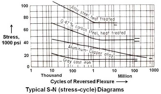
Typical S-N diagrams for some materials are shown in above figure. As shown in the figure, test results are plotted on a semilogarithmic scale with the stress S as the ordinate and the number of cycles N, to cause failure, as the abscissa. The endurance limit of any material is defined as the limiting stress below which the material will withstand an indefinitely large number of cycles of stress without fracture. At that point on the S-N curve, the curve becomes parallel to the abscissa. For some nonferrous materials, however, the curve does not become horizontal. In such circumstances, the term fatigue strength (also known as endurance limit) is often applied to the stress corresponding to some specific number of stress cycles as shown below.
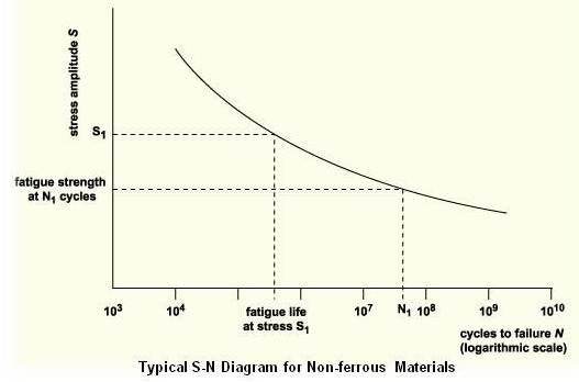
The stress at which failure occurs for a given number of cycles is called the fatigue strength and the number of cycles required for a material to fail at a certain stress in called fatigue life.
Fatigue Fracture
Fatigue failure is brittle-like in nature – even in normally ductile metals – in that there is very little, if any, gross plastic deformation associated with failure. The process occurs by the initiation and propagation of cracks, and the fracture surface is usually perpendicular to the direction of an applied stress.
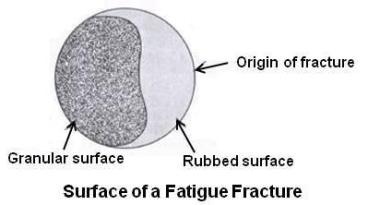
The appearance of a fatigue fracture surface is distinctive and consists of two portions. The smooth or burnished portion shows the progress of the fatigue crack up to the moment of final rupture, and the final granular zone due to fast fracture as shown in the figure given below.
In case of materials that are used for a period of time, allowed to rest for an equivalent time period and then loaded again as in factory usage, the fatigue fracture surface shows Beachmarks as shown in figure given below.
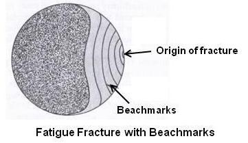
The bands visible in the smooth portion are often referred to as beachmarks. These beachmarks (so called because they resemble ripple marks on a beach) are of macroscopic dimensions – they can be observed with the unaided eye.
An important point regarding fatigue failure is that rubbed surface or beachmarks do not occur on the region over which the final rapid failure occurs as the final fracture possibly occurs as a result of overload. This region of final fracture zone exhibits either ductile or brittle failure – evidence of plastic deformation being present for ductile, and absent for brittle failure.
Thus two portions are evident when investigating a fracture surface due to fatigue. They are called fatigue zone and rupture zone. The fatigue zone is the area of the crack propagation. The area of final failure is called the rupture or instantaneous zone. In investigation of a failed specimen, the rupture zone yields due to overload. The relative size of the rupture zone compared with the fatigue zone relates the degree of overstress applied to the structure. The amount of overstressing can be determined from the fatigue zone as follows:
Highly overstressed if the area of the fatigue zone is very small compared with the area of the rupture zone; medium overstress if the size or area of both zones are nearly equal; low overstress if the area of rupture zone is very small.
The study of fracture mechanisms shows that the growth rate of a crack is proportional to the square root of its length, given the same stress fluctuation and degree of stress concentration. For this reason fatigue cracks spend most of their life as very small cracks which are hard to detect. Only in the last stages of life does the crack start to cause a significant loss of cross-section area, leading to sudden fracture (catastrophic failure).
How Welds Fatigue
In welded steel structures, fatigue cracks will almost certainly start to grow from welds, rather than other details, because:
Most welding processes leave minute metallurgical discontinuities (for example, porosity, under cut, etc.) from which cracks may grow. As a result, the initiation period, which is normally needed to start a crack in plain wrought material, is either very short or does not exist. Cracks therefore spend most of their life propagating, i.e. getting longer.
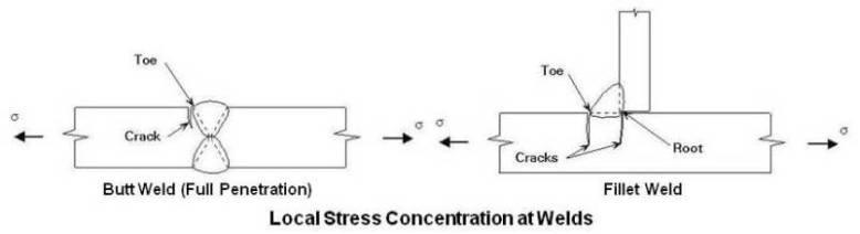
Most structural welds have a rough profile (for example, under cuts). Sharp changes of direction generally occur at the toes of butt welds and at the toes and roots of fillet welds, as shown in the figure given above. These points cause local stress concentrations of the type shown in the figure given below.
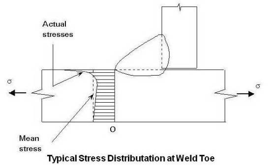
Small discontinuities close to these points will therefore react as though they are in a more highly stressed member and grow faster.
In view of above, it is very important to have good quality of welds free from defects like porosity, sharp under cuts, etc. to prevent failure by fatigue.
Creep
Creep is a property of great importance in materials used for high-temperature applications. It may be defined as a continuing slow plastic flow under constant conditions of load or stress. Due to creep, rate of deformation continues with time under stresses well below the yield strength for the particular temperature to which the metal is subjected.
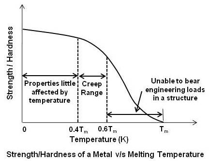
Figure given below shows how in general the strength and hardness of a metal varies with temperature. Tm is the melting temperature of the material. The temperature is measured on the Kelvin scale, whose origin is absolute zero (–273ºC).
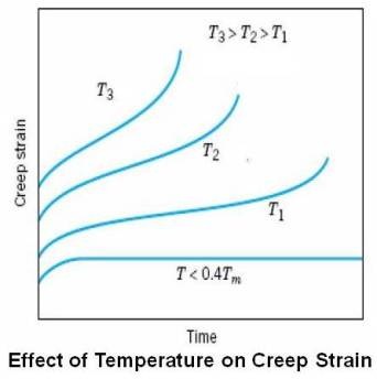
Materials are often placed in service at ‘relatively high temperatures’ and exposed to static mechanical stresses. These stresses are less than the yield strength of the material but nevertheless can cause plastic deformation to take place – particularly over a long period of service time. This phenomenon is known as creep. Note that the term ‘relatively high temperatures’ means high homologous temperatures (Tservice/Tmelting) and is a measure of how near the temperature is to the melting point of the material concerned. Figure given below shows the effect of temperature on creep strain.
Creep is observed in all material types – in metals it only becomes important at temperatures greater than about 0.4Tm (where Tm is the melting point in Kelvin). Soft metals such as tin and lead creep at room temperature while aluminium and its alloys creep at around 250°C. Steel creeps at about 450°C while nickel-based alloys (nimonics) creep at around 650°C.
Creep Test
A creep test is simply a tension test run at constant load and constant temperature. The set up consists of a means of measuring the elongation of the specimen and a means to heat it under closely controlled conditions. On completion of test, the total creep or percent elongation is plotted against time for the entire duration of the test. Two typical creep curves are shown in the figure given below.
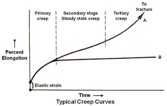
Various stages of creep are illustrated by curve A. The creep strain (elongation) involves three stages designated as primary, secondary, and tertiary as shown by curve A. Each stage may be characterized in terms of creep rate. When the load is first applied, there is an instantaneous elastic elongation. After this, there is a primary creep stage of a transient nature during which slip and work hardening takes place in the most favorably oriented grains. No significant microstructural changes occur in this stage other than movement of dislocations. The creep rate (tangent to the curve) is initially high and gradually slows to a minimum. This is followed by a secondary stage of steady state creep, during which the deformation continues at an approximately constant rate. During this stage a balance exists between the rate of work hardening and the rate of softening because of recovery or recrystallization. In this stage microstructural changes that occur in chromium-molybdenum steels include precipitation and growth of chromium and molybdenum carbides (spheroidization) and formation of first microvoid cavities at carbide particles in grain boundaries.
In some cases under moderate stresses, the creep rate may continue to decrease at very slow rate, and the secondary stage may continue for a very long time as shown by curve B.
In case the stress is sufficiently high, there is a tertiary creep stage in which the creep rate accelerates until fracture occurs. In this stage, voids in grain boundaries link up to form microcracks. The microcracks grow, interconnect to form macrocracks, and finally initiate failure. For most thick section components even the existence of a macrocrack does not necessarily constitute the end of life. A period of stable growth usually occure until a critical crack size is reached, which then leads to rapid failure. Creep damage can be evaluated using metallographic examination methods.
There is little or no correlation between the room-temperature mechanical properties of a material and it creep properties.
Creep seems to be greatly affected by small variations in microstructure (e.g. spheroidization). The grain size of the metal is an important factor in determining its creep characteristics. Whereas at room temperature fine-grained materials show higher yield and ultimate strengths than coarse-grained materials, the reverse is true at elevated temperatures. It is believed that at high temperatures the grain boundaries may act as centers for the generation of dislocations which cause creep.
The presence of solute atoms, even in minor amounts, tends to retard creep by interfering with the motion of dislocations through the crystal. A more potent factor in retarding creep is the presence of a strong, stable, finely dispersed second phase.
Stress Rupture Tests
Rupture tests, properly interpreted, provide a measure of the ultimate load-carrying ability of a material as a function of time. In stress rupture tests the loads are high enough to cause comparatively rapid rupture. A series of specimens are broken at each temperature of interest, under constant loads. The loads (stresses) are selected in such a way that fractures will occur in a few minutes to several hundred hours. The results are plotted in log-log coordinates. The relationship of rupture stress and time taken to rupture is linear if no structural changes occur during the test period. The results are useful to design components for a given period of creep life.
When a piece of high temperature equipment reaches the end of its creep life, simple repairs are not possible and replacement is required.
For more information on creep test, please refer ASTM E139 – Standard Test Methods for Conducting Creep, Creep-Rupture, and Stress-Rupture Tests of Metallic Materials
Design of Components for Creep
The temperature and length of service determines whether or not creep must be considered as a possible mode of failure for a given material component. For example one particular aluminium-copper alloy was used for the forged impellers in the jet engine for an aircraft. In this application, the temperature of operation was up to 200°C and the stress was high enough to limit the life to a few hundred hours. Clearly, in this case, 200°C is a creep-producing temperature. The same alloy is used as the skin for Concorde (aircraft), and over most of this structure the temperature does not exceed 120°C. However, the Concorde airframe is designed for a life in service of 20,000–30,000 hours, and this is a long enough period for 120°C to constitute a possible hazard. Creep is thus important in both applications, even though the temperatures are different.
Over a long period of time components elongate due to creep and may eventually become larger than designed values. This may result in insufficient running clearances for an application. Corrective action shall be taken in such cases.
